Nissan Murano Z51 (2008 year). Manual - part 112


  Index      Manuals     Nissan Murano Z51 (2008 year) - Service and Repair Manual


Search            copyright infringement  


Content      ..     110      111      112      113     ..


Nissan Murano Z51 (2008 year). Manual - part 112


DLK-324

< ON-VEHICLE REPAIR >

[WITH INTELLIGENT KEY SYSTEM]

HOOD

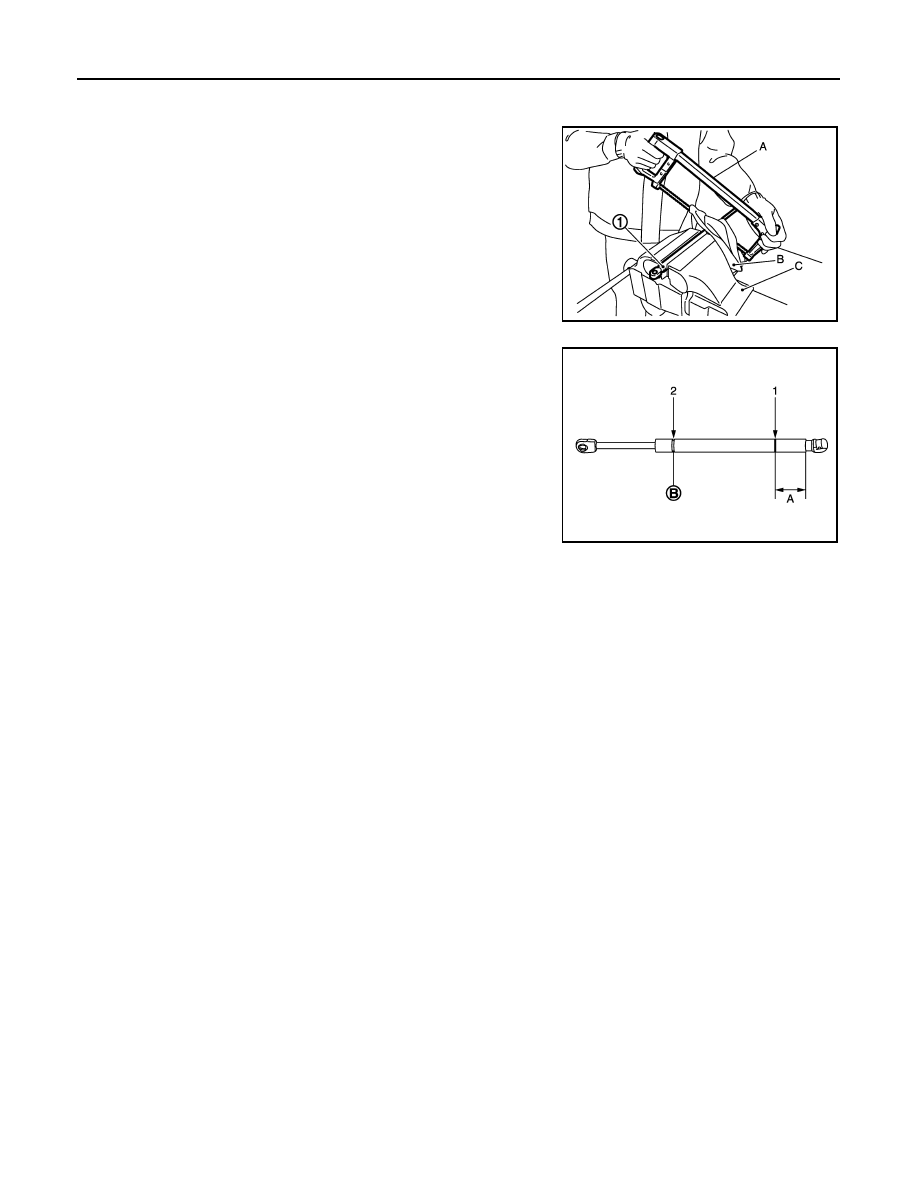
HOOD STAY : Disposal 

INFOID:0000000004747887

1.

Fix hood stay (1) using a vise (C).

2.

Using hacksaw (A) slowly make 2 holes in the hood stay, in
numerical order as shown in the figure.

CAUTION:

• When cutting a hole on hood stay, always cover a hack-

saw using a shop cloth (B) to avoid scattering metal frag-
ments or oil. 

• Wear eye protection (safety glasses).
• Wear gloves.

JMKIA3336ZZ

A:

20 mm (0.787 in)

B:

Cut at the groove.

JMKIA3609ZZ

Revision: 2008 October

2009 Murano

RADIATOR CORE SUPPORT

DLK-325

< ON-VEHICLE REPAIR >

[WITH INTELLIGENT KEY SYSTEM]

C

D

E

F

G

H

I

J

L

M

A

B

DLK

N

O

P

RADIATOR CORE SUPPORT

Exploded View

INFOID:0000000003470304

Removal and Installation

INFOID:0000000003470305

REMOVAL

1.

Use a refrigerant collecting equipment to discharge the refrigerant. Refer to 

HA-25, "Maintenance of

Lubricant Quantity"

.

2.

Remove front under cover. Refer to 

EXT-26, "Removal and Installation"

.

3.

Drain engine coolant from radiator. Refer to 

CO-8, "Draining"

.

4.

Remove front grille. Refer to 

EXT-18, "Removal and Installation"

.

5.

Remove front bumper fascia, energy absorber, bumper reinforcement. Refer to 

EXT-13, "Removal and

Installation"

.

6.

Remove air duct assembly. Refer to 

EM-27, "Exploded View"

.

7.

Remove hood lock. Refer to 

DLK-348, "Removal and Installation"

.

8.

Remove front combination lamp (RH/LH). Refer to 

EXL-174, "Removal and Installation"

 (XENON TYPE)

or 

EXL-337, "Removal and Installation"

 (HALOGEN TYPE).

9.

Disconnect connector of refrigerant pressure sensor. Refer to 

HA-51, "Exploded View"

.

10. Remove bumper retainer assembly. Refer to 

EXT-13, "Removal and Installation"

.

11. Remove clips, and then remove air guide center and air guide upper.
12. Disengage harness clip from air guide side (RH).

13. Disengage pawls, and then remove air guide side (RH/LH).

14. Remove condenser. Refer to 

HA-49, "Removal and Installation"

.

1.

Air guide upper

2.

Air guide side (RH/LH)

3.

Radiator core support

4.

Air guide center

: Pawl

JMKIA1805ZZ

Revision: 2008 October

2009 Murano

DLK-326

< ON-VEHICLE REPAIR >

[WITH INTELLIGENT KEY SYSTEM]

RADIATOR CORE SUPPORT

15. Remove radiator and engine coolant reservoir tank. Refer to 

CO-13, "Removal and Installation"

.

CAUTION:

Operate with two workers, because of it is heavy weight.

16. Disconnect connectors of the following parts.

• Ambient sensor. Refer to 

VTL-25, "Removal and Installation"

.

• Cooling fan (RH/LH) and cooling fan control module. Refer to 

CO-16, "Exploded View"

.

• Crash zone sensor. Refer to 

SR-15, "Removal and Installation"

.

17. Remove radiator upper hose from radiator core support. Refer to 

CO-13, "Exploded View"

.

18. Remove mounting bolt (A) of radiator lower hose bracket (1).

Refer to 

CO-13, "Exploded View"

.

19. Remove radiator lower hose clamp (A) from radiator core sup-

port.

20. Remove power steering oil cooler pipe (1) from radiator core

support.

21. Remove power steering oil cooler pipe clips.  

22. Remove all harness clips from radiator core support.

23. Remove mounting bolts, and then remove radiator core support.

CAUTION:

Never damage power steering oil cooler pipe.

24. Remove the following parts after removing radiator core support.

• Ambient sensor. Refer to 

VTL-25, "Removal and Installation"

.

• Cooling fan (RH/LH) and cooling fan control module. Refer to 

CO-16, "Exploded View"

.

• Crash zone sensor. Refer to 

SR-15, "Removal and Installation"

.

INSTALLATION

Install in the reverse order of removal.

: Vehicle front

JMKIA1915ZZ

: Clip

JMKIA1916ZZ

Revision: 2008 October

2009 Murano

FRONT FENDER

DLK-327

< ON-VEHICLE REPAIR >

[WITH INTELLIGENT KEY SYSTEM]

C

D

E

F

G

H

I

J

L

M

A

B

DLK

N

O

P

FRONT FENDER

Exploded View

INFOID:0000000003470306

Removal and Installation

INFOID:0000000003470307

CAUTION:

Use a shop cloth to protect the body from being damaged during removal and installation.

REMOVAL

1.

Remove clips and remove front fender seal (front/rear).

2.

Remove front grille. Refer to 

EXT-18, "Removal and Installation"

.

3.

Remove front bumper fascia. Refer to 

EXT-13, "Removal and Installation"

.

4.

Remove front combination lamp. Refer to 

EXL-174, "Removal and Installation"

 (XENON TYPE), 

EXL-337,

"Removal and Installation"

 (HALOGEN TYPE).

5.

Remove fender protector. Refer to 

EXT-23, "FENDER PROTECTOR : Removal and Installation"

.

1.

Front fender seal (front)

2.

Front fender seal (rear)

3.

Front fender assembly

4.

Front fender finisher

5.

Insulator

: Clip

: Pawl

JMKIA1806ZZ

Revision: 2008 October

2009 Murano

DLK-328

< ON-VEHICLE REPAIR >

[WITH INTELLIGENT KEY SYSTEM]

FRONT FENDER

6.

Using remover tool (A), remove front fender finisher (1).

7.

Disengage front part of windshield glass molding from front fender.

8.

Remove mounting bolts and remove front fender.

CAUTION:

An viscous urethane foam is installed on the back surface of front fender. When removing the
front fender, peel of the urethane foam bit at a time, and carefully to remove it.

INSTALLATION

Install in the reverse order of removal.

CAUTION:

• After installation, check front fender adjustment. Refer to 

DLK-320, "HOOD ASSEMBLY : Adjust-

ment"

 and 

DLK-330, "DOOR ASSEMBLY : Adjustment"

.

• After installation, apply the touch-up paint (the body color) onto the head of front fender mounting

bolts.

: Clip

: Pawl

JMKIA2261ZZ

Revision: 2008 October

2009 Murano

FRONT DOOR

DLK-329

< ON-VEHICLE REPAIR >

[WITH INTELLIGENT KEY SYSTEM]

C

D

E

F

G

H

I

J

L

M

A

B

DLK

N

O

P

FRONT DOOR

DOOR ASSEMBLY

DOOR ASSEMBLY : Exploded View

INFOID:0000000003470308

DOOR ASSEMBLY : Removal and Installation

INFOID:0000000003470309

CAUTION:

• Perform work with 2 workers, because of its heavy weight.
• When removing and installing front door assembly, support door with a jack and shop cloth to pro-

tect door and body.

REMOVAL

1.

Remove mounting bolts of door check link on the vehicle.

2.

Remove front door harness grommet, and then pull out the harness from the vehicle.

3.

Disconnect front door harness connector.

4.

Remove door hinge mounting nuts (door side), and then remove door assembly.

INSTALLATION

Install in the reverse order of removal.

CAUTION:

• Check front door open/close, lock/unlock operation after installation.
• Check door hinge rotating part for poor lubrication. If necessary, apply body grease.
• After installation, perform the fitting adjustment. Refer to 

DLK-330, "DOOR ASSEMBLY : Adjust-

ment"

.

• After installation, apply touch-up paint (the body color) onto the head of door hinge mounting nuts.

1.

Front door panel

2.

Grommet

3.

Door striker

4.

TORX bolt

5.

Bumper rubber

6.

Door check link

7.

Door hinge (lower)

8.

Door hinge (upper)

Refer to 

GI-4, "Components"

 for symbols in the figure.

JMKIA3688ZZ

Revision: 2008 October

2009 Murano

DLK-330

< ON-VEHICLE REPAIR >

[WITH INTELLIGENT KEY SYSTEM]

FRONT DOOR

DOOR ASSEMBLY : Adjustment

INFOID:0000000003470310

Check the clearance and surface height between front door and each part by visually and touching. 
If the clearance and the surface height are out of specification, adjust them according to the procedures
shown below.

1.

Front fender

2.

Front door 

3.

Rear door

4.

Body side outer

5.

Front door hinge

6.

Rear door hinge (upper)

7.

Rear door hinge (lower)

8.

Door striker

9.

TORX bolt

Refer to 

GI-4, "Components"

 for symbols in the figure.

JMKIA3687GB

Revision: 2008 October

2009 Murano

FRONT DOOR

DLK-331

< ON-VEHICLE REPAIR >

[WITH INTELLIGENT KEY SYSTEM]

C

D

E

F

G

H

I

J

L

M

A

B

DLK

N

O

P

Unit : mm (in)

1.

Remove front fender. Refer to  

DLK-327, "Removal and Installation"

.

2.

Loosen door hinge mounting nuts on door side.

3.

Adjust the surface height of front door according to the fitting standard dimension.

4.

Temporarily tighten door hinge mounting nuts on door side.

5.

Loosen door hinge mounting bolts on body side. 

6.

Raise front door at rear end to adjust clearance of the front door according to the fitting standard dimen-
sion.

7.

After adjustment tighten bolts and nuts to the specified torque.

8.

Install front fender. Refer to refer to 

DLK-327, "Removal and Installation"

.

DOOR STRIKER ADJUSTMENT

Adjust door striker so that it becomes parallel with door lock insertion direction.

DOOR STRIKER

DOOR STRIKER : Exploded View

INFOID:0000000004749747

Portion

Clearance

Surface height

Front fender – Front door

A – A

3.4 – 5.4 (0.134 – 0.213)

- 1.0 – 1.0 (- 0.039 – 0.039)

Front door – Rear door

B – B

3.4 – 5.4 (0.134 – 0.213)

- 1.0 – 1.0 (- 0.039 – 0.039)

Front door – Rear door

G – G

2.9 – 5.9 (0.114 – 0.237)

- 1.5 – 1.5 (- 0.059 – 0.059)

1.

Front door panel

2.

Grommet

3.

Door striker

4.

TORX bolt

5.

Bumper rubber

6.

Door check link

7.

Door hinge (lower)

8.

Door hinge (upper)

Refer to 

GI-4, "Components"

 for symbols in the figure.

JMKIA3688ZZ

Revision: 2008 October

2009 Murano

DLK-332

< ON-VEHICLE REPAIR >

[WITH INTELLIGENT KEY SYSTEM]

FRONT DOOR

DOOR STRIKER : Removal and Installation

INFOID:0000000003470312

REMOVAL

Remove TORX bolts, and then remove door striker.

INSTALLATION

Install in the reverse order of removal.

CAUTION:

• Check front door open/close, lock/unlock operation after installation.
• After installation, be sure to perform the fitting adjustment. Refer to 

DLK-330, "DOOR ASSEMBLY :

Adjustment"

.

DOOR HINGE

DOOR HINGE : Exploded View

INFOID:0000000004749748

DOOR HINGE : Removal and Installation

INFOID:0000000003470314

REMOVAL

1.

Remove front fender. Refer to 

DLK-327, "Removal and Installation"

.

2.

Remove front door assembly. Refer to 

DLK-329, "DOOR ASSEMBLY : Removal and Installation"

.

3.

Remove front door hinge mounting bolts, and then remove front door hinge.

INSTALLATION

Install in the reverse order of removal.

CAUTION:

• Check front door open/close, lock/unlock operation after installation.
• Check door hinge rotating part for poor lubrication. If necessary, apply body grease.

1.

Front door panel

2.

Grommet

3.

Door striker

4.

TORX bolt

5.

Bumper rubber

6.

Door check link

7.

Door hinge (lower)

8.

Door hinge (upper)

Refer to 

GI-4, "Components"

 for symbols in the figure.

JMKIA3688ZZ

Revision: 2008 October

2009 Murano

FRONT DOOR

DLK-333

< ON-VEHICLE REPAIR >

[WITH INTELLIGENT KEY SYSTEM]

C

D

E

F

G

H

I

J

L

M

A

B

DLK

N

O

P

• After installation, perform the fitting adjustment. Refer to 

DLK-330, "DOOR ASSEMBLY : Adjust-

ment"

.

• After installation, apply touch-up paint (the body color) onto the head of door hinge mounting nuts.

DOOR CHECK LINK

DOOR CHECK LINK : Exploded View

INFOID:0000000004749749

DOOR CHECK LINK : Removal and Installation

INFOID:0000000003470316

REMOVAL

1.

Remove front door finisher. Refer to 

INT-11, "FRONT DOOR FINISHER : Removal and Installation"

.

2.

Fully close the front door window.

3.

Remove front door speaker. 

4.

Remove mounting bolts of door check link on the vehicle.

5.

Remove mounting bolts of door check link on door panel.

6.

Take door check link out from the hole of door panel.

INSTALLATION

Install in the reverse order of removal.

CAUTION:

Check front door open/close operation after installation.

1.

Front door panel

2.

Grommet

3.

Door striker

4.

TORX bolt

5.

Bumper rubber

6.

Door check link

7.

Door hinge (lower)

8.

Door hinge (upper)

Refer to 

GI-4, "Components"

 for symbols in the figure.

JMKIA3688ZZ

Revision: 2008 October

2009 Murano

DLK-334

< ON-VEHICLE REPAIR >

[WITH INTELLIGENT KEY SYSTEM]

REAR DOOR

REAR DOOR

DOOR ASSEMBLY

DOOR ASSEMBLY : Exploded View

INFOID:0000000003470317

DOOR ASSEMBLY : Removal and Installation

INFOID:0000000003470318

CAUTION:

• Perform work with 2 workers, because of it’s heavy weight.
• When removing and installing rear door assembly, support door with a jack and shop cloth to pro-

tect door and body.

REMOVAL

1.

Remove mounting bolts of door check link on the vehicle.

2.

Remove rear door harness grommet, and then pull out door harness from the vehicle.

3.

Disconnect rear door harness connector.

4.

Remove door hinge mounting nuts (door side), and then remove rear door assembly.

INSTALLATION

Install in the reverse order of removal.

CAUTION:

• Check rear door open/close, lock/unlock operation after installation.
• Check door hinge rotating part for poor lubrication. If necessary, apply body grease.
• After installation, perform the fitting adjustment. Refer to 

DLK-335, "DOOR ASSEMBLY : Adjust-

ment"

.

• After installation, apply touch-up paint (the body color) onto the head of door hinge mounting nuts.

1.

Rear door panel

2.

Grommet

3.

Door striker

4.

TORX bolt

5.

Bumper rubber

6.

Seal rubber

7.

Door check link

8.

Door hinge (lower)

9.

Door hinge (upper)

Refer to 

GI-4, "Components"

 for symbols in the figure.

JMKIA3686ZZ

Revision: 2008 October

2009 Murano

REAR DOOR

DLK-335

< ON-VEHICLE REPAIR >

[WITH INTELLIGENT KEY SYSTEM]

C

D

E

F

G

H

I

J

L

M

A

B

DLK

N

O

P

DOOR ASSEMBLY : Adjustment

INFOID:0000000003470319

Check the clearance and surface height between rear door and each part by visually and touching. 
If the clearance and the surface height are out of specification, adjust them according to the procedures
shown below.

1.

Front fender

2.

Front door 

3.

Rear door

4.

Body side outer

5.

Front door hinge

6.

Rear door hinge (upper)

7.

Rear door hinge (lower)

8.

Door striker

9.

TORX bolt

Refer to 

GI-4, "Components"

 for symbols in the figure.

JMKIA3687GB

Revision: 2008 October

2009 Murano

DLK-336

< ON-VEHICLE REPAIR >

[WITH INTELLIGENT KEY SYSTEM]

REAR DOOR

Unit: mm (in)

1.

Remove center pillar lower garnish. Refer to 

INT-19, "Removal and Installation"

.

2.

Loosen door hinge mounting nuts on door side.

3.

Adjust the surface height of rear door according to the fitting standard dimension.

4.

Temporarily tighten door hinge mounting nuts on door side.

5.

Loosen door hinge mounting nuts and bolts on body side. 

6.

Raise rear door at rear end to adjust clearance of rear door according to the fitting standard dimension.

7.

After adjustment tighten bolts and nuts to the specified torque.

8.

Install center pillar lower garnish. Refer to 

INT-19, "Removal and Installation"

.

DOOR STRIKER ADJUSTMENT

Adjust door striker so that it becomes parallel with door lock insertion direction.

DOOR STRIKER

DOOR STRIKER : Exploded View

INFOID:0000000004749750

DOOR STRIKER : Removal and Installation

INFOID:0000000003470321

REMOVAL

Portion

Clearance

Surface height

Front door – Rear door

B – B

3.4 – 5.4 (0.134 – 0.213)

-1.0 – 1.0 (-0.039 – 0.039)

Rear door – Body side outer

C – C

3.4 – 5.4 (0.134 – 0.213)

-1.0 – 1.0 (-0.039 – 0.039)

Front door – Rear door

G – G

2.9 – 5.9 (0.114 – 0.237)

-1.5 – 1.5 (-0.059 – 0.059)

1.

Rear door panel

2.

Grommet

3.

Door striker

4.

TORX bolt

5.

Bumper rubber

6.

Seal rubber

7.

Door check link

8.

Door hinge (lower)

9.

Door hinge (upper)

Refer to 

GI-4, "Components"

 for symbols in the figure.

JMKIA3686ZZ

Revision: 2008 October

2009 Murano

REAR DOOR

DLK-337

< ON-VEHICLE REPAIR >

[WITH INTELLIGENT KEY SYSTEM]

C

D

E

F

G

H

I

J

L

M

A

B

DLK

N

O

P

Remove TORX bolts, and then remove door striker.

INSTALLATION

Install in the reverse order of removal.

CAUTION:

• Check rear door open/close, lock/unlock operation after installation.
• After installation, be sure to perform the fitting adjustment. Refer to 

DLK-335, "DOOR ASSEMBLY :

Adjustment"

.

DOOR HINGE

DOOR HINGE : Exploded View

INFOID:0000000004749751

DOOR HINGE : Removal and Installation

INFOID:0000000003470323

REMOVAL

1.

Remove center pillar lower garnish. Refer to 

INT-19, "Removal and Installation"

.

2.

Remove rear door assembly. Refer to 

DLK-334, "DOOR ASSEMBLY : Removal and Installation"

.

3.

Remove rear door hinge mounting bolts and nuts (body side), and then remove door hinge.

INSTALLATION

Install in the reverse order of removal.

CAUTION:

• Check rear door open/close operation after installation.
• Check door hinge rotating part for poor lubrication. If necessary, apply body grease.
• When removing and installing rear door assembly, perform the fitting adjustment. Refer to 

DLK-335,

"DOOR ASSEMBLY : Adjustment"

.

• After installing, apply the touch-up paint (the body color) onto the head of door hinge mounting nuts.

1.

Rear door panel

2.

Grommet

3.

Door striker

4.

TORX bolt

5.

Bumper rubber

6.

Seal rubber

7.

Door check link

8.

Door hinge (lower)

9.

Door hinge (upper)

Refer to 

GI-4, "Components"

 for symbols in the figure.

JMKIA3686ZZ

Revision: 2008 October

2009 Murano

DLK-338

< ON-VEHICLE REPAIR >

[WITH INTELLIGENT KEY SYSTEM]

REAR DOOR

DOOR CHECK LINK

DOOR CHECK LINK : Exploded View

INFOID:0000000004749752

DOOR CHECK LINK : Removal and Installation

INFOID:0000000003470325

REMOVAL

1.

Remove rear door finisher. Refer to 

INT-15, "REAR DOOR FINISHER : Removal and Installation"

.

2.

Fully close the rear door window.

3.

Remove rear door speaker.

4.

Remove mounting bolts of the check link on the vehicle.

5.

Remove mounting bolts of the check link on door panel.

6.

Take door check link out from the hole of door panel.

INSTALLATION

Install in the reverse order of removal.

CAUTION:

Check rear door open/close operation after installation.

1.

Rear door panel

2.

Grommet

3.

Door striker

4.

TORX bolt

5.

Bumper rubber

6.

Seal rubber

7.

Door check link

8.

Door hinge (lower)

9.

Door hinge (upper)

Refer to 

GI-4, "Components"

 for symbols in the figure.

JMKIA3686ZZ

Revision: 2008 October

2009 Murano

BACK DOOR

DLK-339

< ON-VEHICLE REPAIR >

[WITH INTELLIGENT KEY SYSTEM]

C

D

E

F

G

H

I

J

L

M

A

B

DLK

N

O

P

BACK DOOR

BACK DOOR ASSEMBLY

BACK DOOR ASSEMBLY : Exploded View

INFOID:0000000003470326

BACK DOOR ASSEMBLY : Removal and Installation

INFOID:0000000003470327

CAUTION:

Perform work with 2 workers, because of its heavy weight.
NOTE:
The back door harness constitute the back door assembly.

REMOVAL

1.

Remove back door finisher inner, back door hinge cover, back door plate. Refer to 

INT-37, "Removal and

Installation"

1.

Back door stay

2.

Back door hinge

3.

Back door striker

4.

Bumper rubber

5.

Back door weather-strip

6.

Back door assembly

7.

Stud ball

A

: Center mark

B

: Front mark

: Vehicle front

Refer to 

GI-4, "Components"

 for symbols in the figure.

JMKIA3496ZZ

Revision: 2008 October

2009 Murano


Content      ..     110      111      112      113     ..