Nissan Murano Z51 (2008 year). Manual - part 64
BCS-8
< FUNCTION DIAGNOSIS >
BODY CONTROL SYSTEM
Component Parts Location
INFOID:0000000003441351
Nissan Vehicle Immobilizer System
(NVIS) - NATS (Without Intelligent Key
system)
Engine start function
SEC-244, "ENGINE START FUNCTION : System Diagram"
Warning function
SEC-248, "WARNING FUNCTION : System Description"
Vehicle security system
•
(With Intelligent Key system)
•
(Without Intelligent Key system)
Panic alarm
Rear window defogger system
•
DEF-4, "WITH BOSE SYSTEM : System Diagram"
BOSE system)
•
DEF-6, "WITHOUT BOSE SYSTEM : System Diagram"
(With-
out BOSE system)
Remote keyless entry system (Without Intelligent Key system)
Intelligent Key system/engine start system
Door lock function
DLK-22, "INTELLIGENT KEY SYSTEM : System Diagram"
Back door function
Remote keyless entry
function
Key reminder function
Warning function
Engine start function
Power window system
Retained accessory power (RAP) system
Tire pressure monitor system (TPMS) - AIR PRESSURE MONI-
TOR
System
Reference
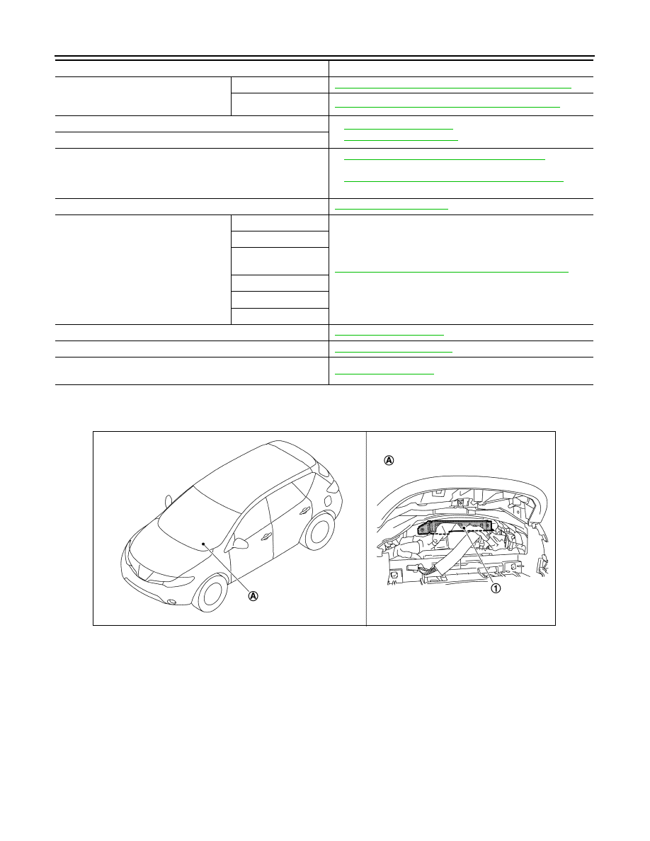
1.
BCM
A.
Behind of combination meter
JPMIA0897ZZ
Revision: 2008 October
2009 Murano