Nissan Murano Z51 (2008 year). Manual - part 56


  Index      Manuals     Nissan Murano Z51 (2008 year) - Service and Repair Manual


Search            copyright infringement  


Content      ..     54      55      56      57     ..


Nissan Murano Z51 (2008 year). Manual - part 56


AV

AV CONTROL UNIT

AV-669

< ECU DIAGNOSIS >

[BOSE AUDIO WITH NAVIGATION]

C

D

E

F

G

H

I

J

K

L

M

B

A

O

P

Display

The messages displayed on fail-safe conditions are as shown below:

DESCRIPTION OF CONTROLS

Ability Operation Mode 

There is an ability operation mode for Fail-safes due to low or high ambiance temperature.
If HDD data can be read, fail-safe is shown, then normal displays are displayed only for functions which can be
operated.

RELEASE CONDITIONS OF FAIL-SAFE 

Fail-safe is released on the following conditions and normal mode is restored.

When the temperature of HDD is low or high.

If the ambient temperature becomes out of the fail-safe conditional range, normal mode is restored.

When HDD is malfunctioning.

If the malfunction disappears, normal mode is restored.
NOTE:
•  If fail-safe mode due to HDD malfunction is seen continuously, replace AV control unit.
•  If fail-safe mode due to HDD malfunction is seen temporarily, check the “Error History” of Confirmation/

Adjustment mode. If this is normal, then continue the normal operation, observing the function. (It might be a
temporary malfunction of HDD.)

JPNIA0414GB

Fail-safe mode

Display (display of the fail-safe condition)

When HDD temperature is low

HDD system is experiencing problems due to extreme low temperature.
Normal operation will resume when temperature rises.

When HDD temperature is high

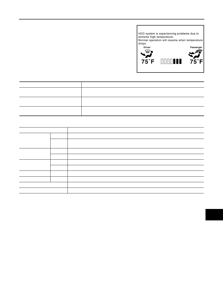
HDD system is experiencing problems due to extreme high temperature.
Normal operation will resume when temperature drops.

When HDD is malfunctioning

HDD system is not functioning.
Please contact your dealer for assistance.

Function

When Fail-safe Function is activated 

Air conditioner

Operation

Only multifunction switch (preset switch) can be operated.

Display

• LED of multifunction switch (preset switch) illuminates.
• Aimed temperature, blow angle, and flow rate are displayed in simplified mode. 

Audio

Operation

Only ON/OFF and volume control operations by multifunction switch (preset switch) are possible.

Display

No display (“Fail-safe mode” is displayed.)

Camera

Operation

Image tone cannot be controlled.

Display

Cannot be superimposed. (warning display, tone control display)

Hands-free phone

Operation

Cannot be operated.

Navigation

Operation

Cannot be operated.

Self diagnosis

The display in simplified mode of fail-safe condition

CONSULT-III diagnosis

Cannot be operated.

Revision: 2008 October

2009 Murano

AV-670

< ECU DIAGNOSIS >

[BOSE AUDIO WITH NAVIGATION]

AV CONTROL UNIT

DTC Index

INFOID:0000000003457764

SELF-DIAGNOSIS RESULTS DISPLAY ITEM

NOTE:

DTC

Display item

Refer to

U1000

CAN COMM CIRCUIT [U1000]

AV-593, "Diagnosis Procedure"

U1010

CONTROL UNIT (CAN) [1010]

AV-594, "Diagnosis Procedure"

U1310

CONTROL UNIT (AV) [U1310]

AV-595, "DTC Logic"

U1200

Control Unit FLASH-ROM [1200]

AV-596, "DTC Logic"

U1201

Gyro NO CONN [1201]

AV-597, "DTC Logic"

U1216

CAN CONT [U1216]

AV-598, "DTC Logic"

U1217

BLUETOOTH CONN [U1217]

AV-599, "DTC Logic"

U1218

HDD CONN [U1218]

AV-600, "DTC Logic"

U1219

HDD READ [U1219]

AV-601, "DTC Logic"

U1220

XM SERIAL COMM [U1220]

AV-602, "DTC Logic"

U121A

HDD WRITE [U121A]

AV-603, "DTC Logic"

U121B

HDD COMM [U121B]

AV-604, "DTC Logic"

U121C

HDD ACCESS [U121C]

AV-605, "DTC Logic"

U121D

DSP CONN [U121D]

AV-606, "DTC Logic"

U121E

DSP COMM [U121E]

AV-607, "DTC Logic"

U121F

INTERNAL COMM [U121F]

AV-608, "DTC Logic"

U1204

GPS COMM [U1204]

AV-609, "DTC Logic"

U1205

GPS ROM [U1205]

AV-610, "DTC Logic"

U1206

GPS RAM [U1206]

AV-611, "DTC Logic"

U1207

GPS RTC [U1207]

AV-612, "DTC Logic"

U1243

FRONT DISP CONN [U1243]

AV-613, "DTC Logic"

U1244

GPS ANTENNA CONN [U1244]

AV-615, "DTC Logic"

U1250

CAMERA CONT. CONN [U1250]

AV-616, "DTC Logic"

U1258

XM ANTENNA CONN [U1258]

AV-617, "DTC Logic"

U1300
U121F

• AV COMM CIRCUIT [U1300]
• INTERNAL COMM [U121F]

AV-618, "Description"

U1300
U1240

• AV COMM CIRCUIT [U1300]
• SWITCH CONN [U1240]

AV-618, "Description"

U1300
U1252

• AV COMM CIRCUIT [U1300]
• REAR CAMERA LAN CONN [U1252]

AV-618, "Description"

U1300
U1254

• AV COMM CIRCUIT [U1300]
• IPOD CONN [U1254]

AV-618, "Description"

U1300
U1252

U1254

*

• AV COMM CIRCUIT [U1300]
• REAR CAMERA LAN CONN [U1252]

• IPOD CONN [U1254]

*

AV-618, "Description"

U1300
U1240
U1252

U1254

*

• AV COMM CIRCUIT [U1300]
• SWITCH CONN [U1240]
• REAR CAMERA LAN CONN [U1252]

• IPOD CONN [U1254]

*

AV-618, "Description"

U1300
U121F
U1240
U1252

U1254

*

• AV COMM CIRCUIT [U1300]
• INTERNAL COMM [U121F]
• SWITCH CONN [U1240]
• REAR CAMERA LAN CONN [U1252]

• IPOD CONN [U1254]

*

AV-618, "Description"

Revision: 2008 October

2009 Murano

AV

AV CONTROL UNIT

AV-671

< ECU DIAGNOSIS >

[BOSE AUDIO WITH NAVIGATION]

C

D

E

F

G

H

I

J

K

L

M

B

A

O

P

*: Non-equipped item is not displayed.

Revision: 2008 October

2009 Murano

AV-672

< ECU DIAGNOSIS >

[BOSE AUDIO WITH NAVIGATION]

FRONT DISPLAY UNIT

FRONT DISPLAY UNIT

Reference Values

INFOID:0000000003457765

TERMINAL LAYOUT

PHYSICAL VALUES

JPNIA0006ZZ

Terminal

(Wire color)

Description

Condition

Reference value

(Approx.)

+

Signal name

Input/

Output

1

(B)

Ground

Ground

Ignition 

switch 

ON 

0  V

2

(Y)

Ground

Battery power supply

Input

Ignition 

switch 

OFF

Battery voltage

3

(R)

Ground

ACC power supply

Input

Ignition 

switch 

ACC

Battery voltage

4

Shield

5

(B)

Ground

AUX image ground

Ignition 

switch 

ON 

0  V

6

(R)

Ground

RGB image signal (G: 
green)

Input

Ignition 

switch 

ON

Start confirmation/adjust-
ment mode, and then dis-
play color bar by selecting 
“Color Spectrum Bar” on 
DISPLAY DIAGNOSIS 
screen.

7

Shield

8

(B)

Ground

Horizontal synchronizing 
(HP) signal

Output

Ignition 

switch 

ON

JSNIA1030ZZ

SKIB3601E

Revision: 2008 October

2009 Murano

AV

FRONT DISPLAY UNIT

AV-673

< ECU DIAGNOSIS >

[BOSE AUDIO WITH NAVIGATION]

C

D

E

F

G

H

I

J

K

L

M

B

A

O

P

9

(W)

Ground

RGB area (YS) signal

Input

Ignition 

switch 

ON

When RGB image is dis-
played.

5.0 V

When rear view camera im-
age is displayed.

11

(R)

Ground

Communication signal
(CONT

DISP)

Input

Ignition 

switch 

ON

When adjusting display 
brightness.

12

(W)

14

Camera image signal

Input

Ignition 

switch 

ON

When rear view camera im-
age is displayed.

13

(B)

Ground

Ground

Ignition 

switch 

ON

0  V

14

Ground

Shield (camera image 
ground

Ignition 

switch 

ON

0  V

15

(Y)

5

AUX image signal

Input

Ignition 

switch 

ON

When AUX image is dis-
played.

17

(G)

Ground

RGB image signal (R: red)

Input

Ignition 

switch 

ON

Start confirmation/adjust-
ment mode, and then dis-
play color bar by selecting 
“Color Spectrum Bar” on 
DISPLAY DIAGNOSIS 
screen.

Terminal

(Wire color)

Description

Condition

Reference value

(Approx.)

+

Signal name

Input/

Output

PKIB4948J

PKIB5039J

SKIB2251J

SKIB2251J

JSNIA1029ZZ

Revision: 2008 October

2009 Murano

AV-674

< ECU DIAGNOSIS >

[BOSE AUDIO WITH NAVIGATION]

FRONT DISPLAY UNIT

Wiring Diagram - BOSE AUDIO WITH NAVIGATION SYSTEM -

INFOID:0000000003702902

NOTE:

18

(W)

Ground

RGB image signal (B: blue)

Input

Ignition 

switch 

ON

Start confirmation/adjust-
ment mode, and then dis-
play color bar by selecting 
“Color Spectrum Bar” on 
DISPLAY DIAGNOSIS 
screen.

19

(B)

Ground

RGB synchronizing signal

Input

Ignition 

switch 

ON

20

(R)

Ground

Vertical synchronizing (VP) 
signal

Output

Ignition 

switch 

ON

21

Shield

22

(G)

Ground

Communication signal
(DISP

CONT)

Output

Ignition 

switch 

ON

When adjusting display 
brightness.

23

Shield

Terminal

(Wire color)

Description

Condition

Reference value

(Approx.)

+

Signal name

Input/

Output

JSNIA1031ZZ

JPNIA0461GB

SKIB3598E

PKIB5039J

Revision: 2008 October

2009 Murano

AV

FRONT DISPLAY UNIT

AV-675

< ECU DIAGNOSIS >

[BOSE AUDIO WITH NAVIGATION]

C

D

E

F

G

H

I

J

K

L

M

B

A

O

P

In this section, PRESET SWITCH and MULTIFUNCTION SWITCH are written as the MULTIFUNCTION
SWITCH.

JCNWM1838GB

Revision: 2008 October

2009 Murano

AV-676

< ECU DIAGNOSIS >

[BOSE AUDIO WITH NAVIGATION]

FRONT DISPLAY UNIT

JCNWM1839GB

Revision: 2008 October

2009 Murano

AV

FRONT DISPLAY UNIT

AV-677

< ECU DIAGNOSIS >

[BOSE AUDIO WITH NAVIGATION]

C

D

E

F

G

H

I

J

K

L

M

B

A

O

P

JCNWM1840GB

Revision: 2008 October

2009 Murano

AV-678

< ECU DIAGNOSIS >

[BOSE AUDIO WITH NAVIGATION]

FRONT DISPLAY UNIT

JCNWM1841GB

Revision: 2008 October

2009 Murano

AV

FRONT DISPLAY UNIT

AV-679

< ECU DIAGNOSIS >

[BOSE AUDIO WITH NAVIGATION]

C

D

E

F

G

H

I

J

K

L

M

B

A

O

P

JCNWM1842GB

Revision: 2008 October

2009 Murano

AV-680

< ECU DIAGNOSIS >

[BOSE AUDIO WITH NAVIGATION]

FRONT DISPLAY UNIT

JCNWM1843GB

Revision: 2008 October

2009 Murano

AV

FRONT DISPLAY UNIT

AV-681

< ECU DIAGNOSIS >

[BOSE AUDIO WITH NAVIGATION]

C

D

E

F

G

H

I

J

K

L

M

B

A

O

P

JCNWM1844GB

Revision: 2008 October

2009 Murano

AV-682

< ECU DIAGNOSIS >

[BOSE AUDIO WITH NAVIGATION]

FRONT DISPLAY UNIT

JCNWM1845GB

Revision: 2008 October

2009 Murano

AV

FRONT DISPLAY UNIT

AV-683

< ECU DIAGNOSIS >

[BOSE AUDIO WITH NAVIGATION]

C

D

E

F

G

H

I

J

K

L

M

B

A

O

P

JCNWM1846GB

Revision: 2008 October

2009 Murano

AV-684

< ECU DIAGNOSIS >

[BOSE AUDIO WITH NAVIGATION]

FRONT DISPLAY UNIT

JCNWM1847GB

Revision: 2008 October

2009 Murano


Content      ..     54      55      56      57     ..