Nissan Murano Z51 (2008 year). Manual - part 49
AV
MULTI AV SYSTEM
AV-557
< FUNCTION DIAGNOSIS >
[BOSE AUDIO WITH NAVIGATION]
C
D
E
F
G
H
I
J
K
L
M
B
A
O
P
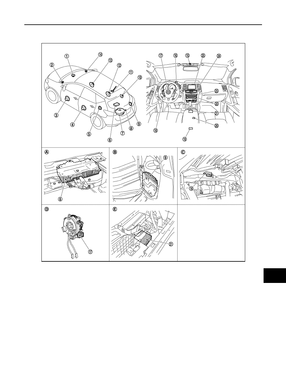
Component Parts Location
INFOID:0000000003356550
1.
Center speaker
2.
Front squawker LH
3.
Front door speaker LH
4.
Rear door speaker LH
5.
Rear speaker LH
6.
BOSE amp.
7.
Woofer
8.
Rear view camera
9.
Camera control unit
10. Rear speaker RH
11.
Antenna base (antenna amp. and
satellite antenna)
12. Rear door speaker RH
13. Front door speaker RH
14. Front squawker RH
15. Microphone
16. GPS antenna
17. Steering angle sensor
18. Steering switch
19. Auxiliary input jacks
20. iPod connector
21. iPod adapter
22. Preset switch
23. AV control unit
24. Multifunction switch
25. Front display unit
A.
Luggage floor finisher is removed
condition
B.
Luggage side finisher lower RH is re-
moved condition
C.
Combination meter is removed condi-
tion
D.
Spiral cable part
E.
Console finisher is removed condition
JSNIA1096ZZ
Revision: 2008 October
2009 Murano