Nissan Murano Z51 (2008 year). Manual - part 16
AV
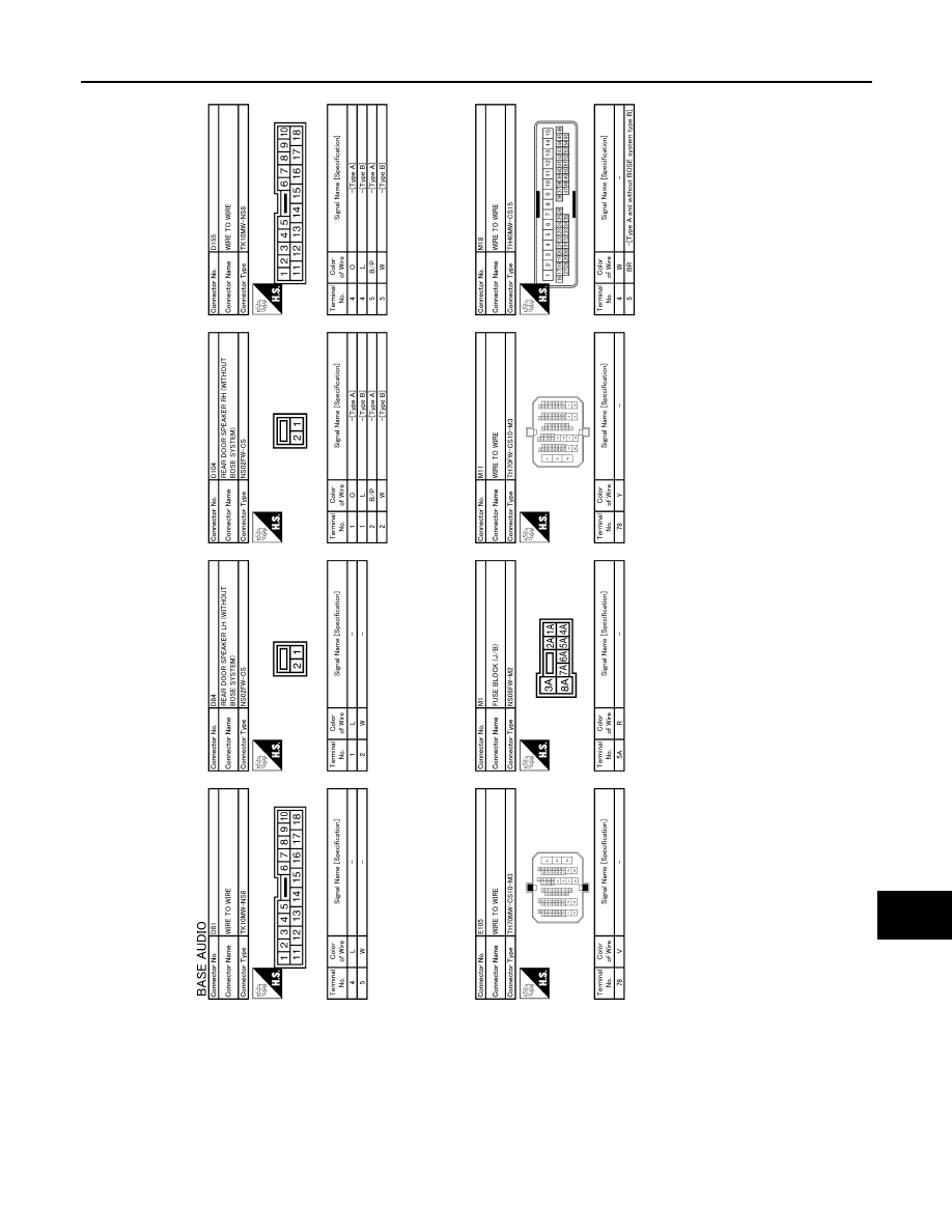
AUDIO UNIT
AV-29
< ECU DIAGNOSIS >
[BASE AUDIO]
C
D
E
F
G
H
I
J
K
L
M
B
A
O
P
JCNWM1835GB
Revision: 2008 October
2009 Murano
|
|
|
AV AUDIO UNIT AV-29 < ECU DIAGNOSIS > [BASE AUDIO] C D E F G H I J K L M B A O P JCNWM1835GB Revision: 2008 October 2009 Murano |