Infiniti FX35, FX50 (S51). Manual - part 988
EM-252
< UNIT DISASSEMBLY AND ASSEMBLY >
[VK50VE]
CYLINDER HEAD
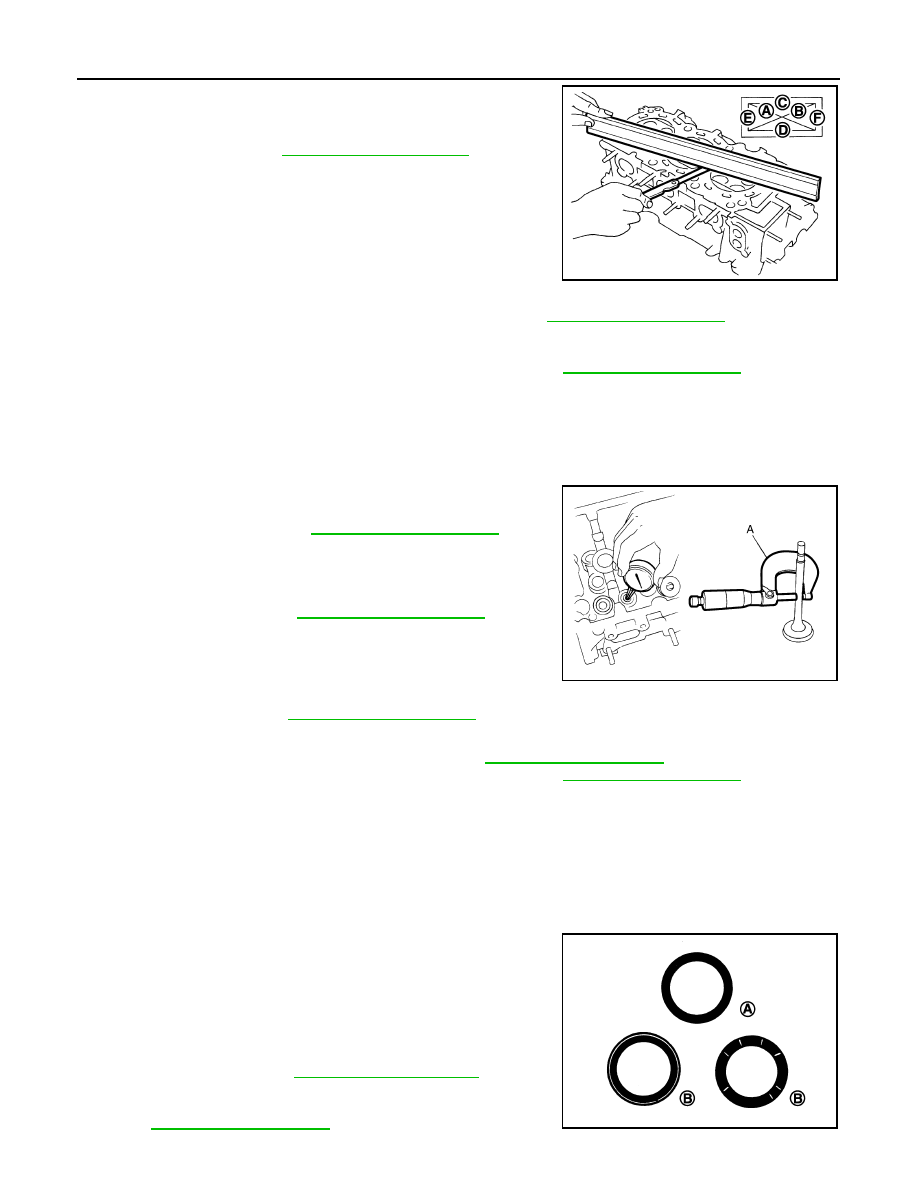
2.
At each of several locations on bottom surface of cylinder head,
measure the distortion in six directions (A, B, C, D, E, F).
• If it exceeds the limit, replace VVEL ladder assembly & cylinder
head assembly.
NOTE:
Cylinder head assembly cannot be replaced as a single part,
because it is machined together with VVEL ladder assembly.
Valve Dimensions
• Check the dimensions of each valve. For the dimensions, refer to
.
• If dimensions are out of the standard.
- Replace valve (EXH) and check valve seat contact. Refer to "VALVE SEAT CONTACT". (Exhaust side)
- Replace VVEL ladder assembly & cylinder head assembly. Refer to
. (Intake side)
NOTE:
Since the valve (INT) cannot be replaced by the piece, VVEL ladder assembly & cylinder head assembly
replacement are required.
Valve Guide Clearance
Valve Stem Diameter
• Measure the diameter of valve stem with micrometer (A).
Valve Guide Inner Diameter
• Measure the inner diameter of valve guide with bore gauge.
Valve Guide Clearance
• (Valve guide clearance) = (Valve guide inner diameter) – (Valve
stem diameter)
• If the calculated value exceeds the limit.
- Replace valve (EXH) and/or valve guide (EXH). Refer to
- Replace VVEL ladder assembly & cylinder head assembly. Refer to
. (Intake side)
NOTE:
Since the valve (INT) and valve guide (INT) cannot be replaced by the piece, VVEL ladder assembly & cylin-
der head assembly replacement are required.
Valve Seat Contact
• After confirming that the dimensions of valve guides and valves are within the specifications, perform this
procedure.
• Apply prussian blue (or white lead) onto contacting surface of valve seat to check the condition of the valve
contact on the surface.
• Check if the contact area band is continuous all around the circum-
ference.
- If not, grind to adjust valve fitting and check again. If the contacting
surface still has “NG” conditions even after the re-check, replace
valve seat (EXH). Refer to
side)
- If not, replace VVEL ladder assembly & cylinder head assembly.
. (Intake side)
Limit
: Refer to
.
JPBIA0176ZZ
Standard :
Standard
: Refer to
.
Standard
: Refer to
JPBIA0183ZZ
A
: OK
B
: NG
JPBIA0187ZZ