Infiniti FX35, FX50 (S51). Manual - part 981


  Index      Infiniti     Infiniti FX35, FX50 (S51) - service repair manual 2010 year


Search            


Content   ..  979  980  981  982   ..


Infiniti FX35, FX50 (S51). Manual - part 981


EM-224

< UNIT DISASSEMBLY AND ASSEMBLY >

[VK50VE]

TIMING CHAIN

a.

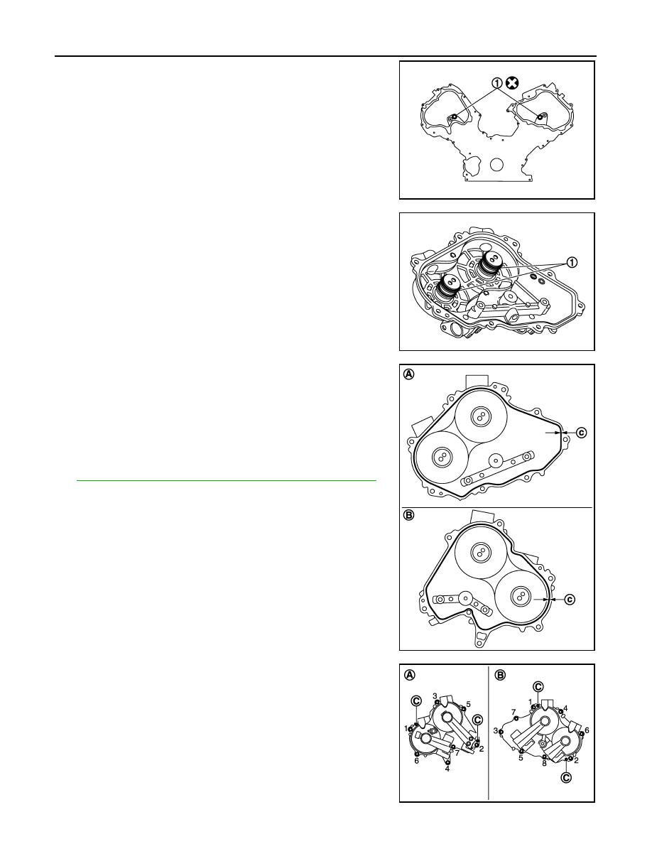
Install new O-rings (1) on front cover.

b.

Install new seal rings (1) in shaft grooves.

CAUTION:

When replacing seal ring, replace all rings with new ones.

c.

Apply a continuous bead of liquid gasket with tube presser
(commercial service tool) to valve timing control covers as
shown in the figure.

Use Genuine RTV Silicone Sealant or equivalent. Refer to

GI-16, "Recommended Chemical Products and Sealants"

.

d.

Being careful not to move seal ring from the installation groove,
align dowel pins on front cover with dowel pin holes (C) to install
valve timing control covers.

e.

Tighten mounting bolts in numerical order as shown in the fig-
ure.

JPBIA2117ZZ

JPBIA2103ZZ

A

:  Bank  1

B

:  Bank  2

c

φ

3.4 - 4.4 mm (0.134 - 0.173 in)

JPBIA2104ZZ

A

:  Bank  2

B

:  Bank  1

JPBIA2118ZZ

TIMING CHAIN

EM-225

< UNIT DISASSEMBLY AND ASSEMBLY >

[VK50VE]

C

D

E

F

G

H

I

J

K

L

M

A

EM

N

P

O

13. Install camshaft position sensor and valve timing control solenoid valve (RH and LH) to valve timing con-

trol cover, if removed.
• Be sure to tighten mounting bolts with flanges completely seated.

14. Install oil pan (lower) and oil strainer. Refer to 

EM-188, "Exploded View"

.

15. Install oil pan (upper). Refer to 

EM-208, "Exploded View"

.

16. Install water pump pulley. Refer to 

CO-44, "Exploded View"

.

17. Install crankshaft pulley. 

• Fix the crankshaft as instructed in the removal procedure. Refer to 

EM-194, "FRONT OIL SEAL :

Removal and Installation"

.

a.

Install crankshaft pulley, taking care not to damage front oil seal.

b.

Apply engine oil onto threaded parts of crankshaft pulley bolt and seating area.
• Lightly tapping its center with plastic hammer, insert crankshaft pulley.

CAUTION:

Never tap crankshaft pulley on the side surface where belt is installed (outer circumference).

c.

Tighten crankshaft pulley bolt.

d.

Put a paint mark (A) on crankshaft pulley (1) aligning with angle
mark (B) on crankshaft pulley bolt. 

e.

Tighten crankshaft pulley bolt (clockwise).

• Check the tightening angle by referencing to the notches. The

angle between two notches is 90 degrees.

18. Rotate crankshaft pulley in normal direction (clockwise when viewed from engine front) to confirm it turns

smoothly.

19. Install in the reverse order of removal.

Inspection

INFOID:0000000005245252

INSPECTION AFTER DISASSEMBLY

Timing Chain

Check for cracks and any excessive wear at link plates and roller
links of timing chain. Replace timing chain if necessary.

INSPECTION AFTER ASSEMBLY

Inspection for Leakage

The following are procedures for checking fluid leakage, lubricant leakage.

• Before starting engine, check oil/fluid levels including engine coolant and engine oil. If any are less than the

required quantity, fill them to the specified level. Refer to 

MA-12, "Fluids and Lubricants"

.

• Follow the procedure below to check for fuel leakage.

 : 157 N·m (16 kg-m, 116 ft-lb)

 Angle tightening: 90 degrees (c)

JPBIA2066ZZ

A

:  Crack

B

:  Wear

JPBIA0091ZZ

EM-226

< UNIT DISASSEMBLY AND ASSEMBLY >

[VK50VE]

TIMING CHAIN

- Turn ignition switch to the “ON” position (with engine stopped). With fuel pressure applied to fuel piping,

check for fuel leakage at connection points.

- Start engine. With engine speed increased, check again for fuel leakage at connection points.
• Run engine to check for unusual noise and vibration.

NOTE:
If hydraulic pressure inside chain tensioner drops after removal/installation, slack in guide may generate a
pounding noise during and just after the engine start. However, this does not indicate a malfunction. The
noise will stop after hydraulic pressure rises.

• Warm up engine thoroughly to check that there is no leakage of fuel, or any oil/fluids including engine oil and

engine coolant.

• Bleed air from lines and hoses of applicable lines, such as in cooling system.
• After cooling down engine, again check oil/fluid levels including engine oil and engine coolant. Refill them to

the specified level, if necessary.

Summary of the inspection items:

* Transmission/transaxle/CVT fluid, power steering fluid, brake fluid, etc.

Items

Before starting engine

Engine running

After engine stopped

Engine coolant

Level

Leakage

Level

Engine oil

Level

Leakage

Level

Other oils and fluids*

Level

Leakage

Level

Fuel

Leakage

Leakage

Leakage

CAMSHAFT

EM-227

< UNIT DISASSEMBLY AND ASSEMBLY >

[VK50VE]

C

D

E

F

G

H

I

J

K

L

M

A

EM

N

P

O

CAMSHAFT

Exploded View

INFOID:0000000005245253

CAUTION:

A high degree of precision is required for a valve on the intake side. Never remove the valve related
parts unless necessary.
NOTE:
• As for replacement of parts on the intake side as shown in the exploded view, replace VVEL ladder assem-

bly & cylinder head assembly. 

1.

VVEL control shaft position sensor 
(bank 2)

2.

VVEL actuator sub assembly (bank 2) 3.

VVEL ladder assembly (bank 2)

4.

Dowel pin

5.

Actuator bracket (rear) (bank 2)

6.

Washer

7.

Camshaft (EXH) (bank 2)

8.

Cylinder head (bank 2)

9.

Valve lifter (INT)

10. Cylinder head (bank 1)

11.

Camshaft (EXH) (bank 1)

12. Actuator cover

13. Valve lifter (EXH)

14.

VVEL ladder assembly (bank 1)

15. VVEL actuator sub assembly (bank 1)

16.

VVEL control shaft position sensor 
(bank 1)

17.

Actuator bracket (rear) (bank 1)

A.

Refer to 

EM-228

Refer to 

GI-4, "Components"

 for symbol marks in the figure.

JPBIA2124GB


Content   ..  979  980  981  982   ..