Infiniti FX35, FX50 (S51). Manual - part 979


  Index      Infiniti     Infiniti FX35, FX50 (S51) - service repair manual 2010 year


Search            


Content   ..  977  978  979  980   ..


Infiniti FX35, FX50 (S51). Manual - part 979


EM-216

< UNIT DISASSEMBLY AND ASSEMBLY >

[VK50VE]

TIMING CHAIN

NOTE:
To remove timing chain and related parts, start with those on bank 1. The procedure for removing parts on
bank 2 is omitted because it is the same as that for bank 1. 

a.

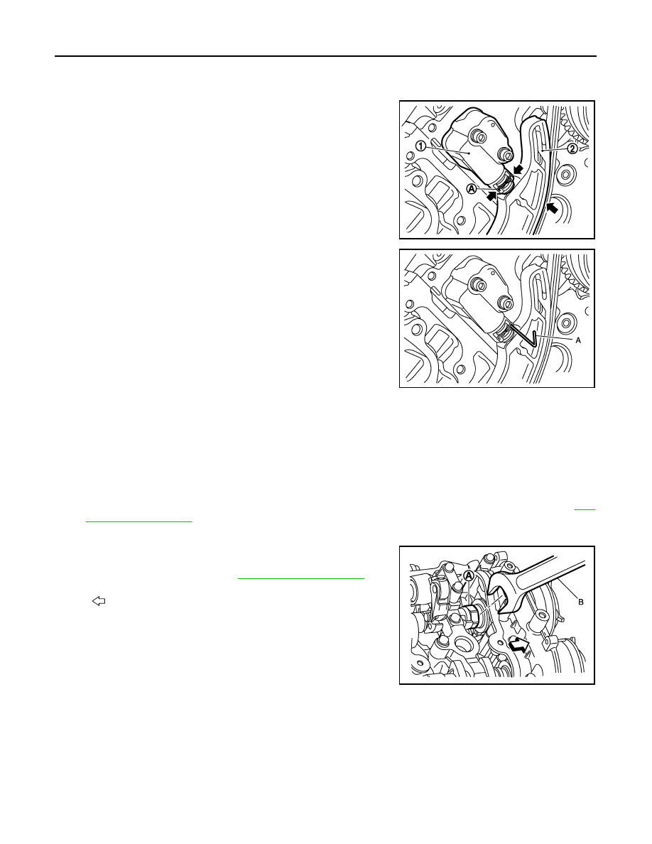
Push both sides of spring (A) against spring tension, and then
press in plunger with a slack guide (2).

b.

Insert a stopper pin (A) into the body hole, and then fix it with the
plunger pushed in.

22. Remove tension guide and slack guide.

23. Remove timing chain and crankshaft sprocket.

CAUTION:

After removing timing chain, never turn crankshaft and camshaft separately, or valves will strike
the piston head.

24. Remove camshaft sprocket (INT) and (EXH) as per the following:

Exhaust side:

• Secure the hexagonal portion of camshaft (EXH) using a wrench to loosen mounting bolt. Refer to 

EM-

227, "Exploded View"

.

Intake side:

• Secure the hexagonal portion (located in between journal No.1

and journal No. 2) of drive shaft (A) using a wrench (B) to
loosen mounting bolt. Refer to 

EM-227, "Exploded View"

.

NOTE:
The figure shows an example of bank 2.

CAUTION:

• Never loosen the mounting bolt by securing anything other than the camshaft (drive shaft) hexago-

nal portion or with tensioning the timing chain.

• When holding the hexagonal part of camshaft (drive shaft) with a wrench, be careful not to allow the

wrench to cause interference with other parts.

1

: Timing chain tensioner (bank 1)

JPBIA2369ZZ

JPBIA2370ZZ

: Engine front

JPBIA2302ZZ

TIMING CHAIN

EM-217

< UNIT DISASSEMBLY AND ASSEMBLY >

[VK50VE]

C

D

E

F

G

H

I

J

K

L

M

A

EM

N

P

O

• Never disassemble camshaft sprocket. [Never loosen bolts

(C), (D) as shown in the figure.]

25. Use scraper to remove all traces of old liquid gasket from front cover and opposite mating surfaces.

• Remove old liquid gasket from bolt hole and thread.

ASSEMBLY

A

:  Intake 

B

: Exhaust

JPBIA2111ZZ

A

: Remove old liquid gasket that is stuck

B

: Bolt hole

JPBIA0051ZZ

EM-218

< UNIT DISASSEMBLY AND ASSEMBLY >

[VK50VE]

TIMING CHAIN

NOTE:
• The above figure shows the relationship between the matching mark on each timing chain and that on the

corresponding sprocket, with the components installed.

• Parts with an identification mark (R or L) should be installed on the corresponding bank according to the

mark. 

- Camshaft sprocket (INT), camshaft sprocket (EXH)
- Tension guide
- Slack guide
• To install timing chain and related parts, start with those on bank 2. The procedure for installing parts on

bank 1 is omitted because it is the same as that for installation on bank 2.

• There is no matching mark in the oil pump related parts.

1.

Timing chain

2.

Camshaft sprocket (INT) (bank 2)

3.

Camshaft sprocket (EXH) (bank 2)

4.

Slack guide (bank 2)

5.

Timing chain tensioner (bank 2)

6.

Oil pump drive chain

7.

Oil pump sprocket (oil pump side)

8.

Oil pump drive chain tensioner

9.

Oil pump sprocket (crankshaft side)

10.

Tension guide (bank 1)

11. Camshaft sprocket (EXH) (bank 1)

12.

Camshaft sprocket (INT) (bank 1)

13.

Timing chain tensioner (bank 1)

14. Slack guide (bank 1)

15.

Tension guide (bank 2)

16.

Crankshaft sprocket (bank 2 side)

17. Crankshaft sprocket (bank 1 side)

A.

Crankshaft key

B.

Matching mark (outer groove)

C.

Matching mark (copper link)

D.

Matching mark (punched)

E.

Matching mark (yellow link)

F.

Matching mark (notched)

JPBIA2112ZZ

TIMING CHAIN

EM-219

< UNIT DISASSEMBLY AND ASSEMBLY >

[VK50VE]

C

D

E

F

G

H

I

J

K

L

M

A

EM

N

P

O

1.

Check that crankshaft key (1) and dowel pin (A) of each cam-
shaft are located as shown in the figure.

NOTE:
Though camshaft does not stop at the position as shown in the
figure, for the placement of cam nose, it is generally accepted
camshaft is placed for the same direction of the figure.

2.

Install camshaft sprockets (INT and EXH).
• Install onto correct side by checking with identification mark

(A) on surface.

Exhaust side:

• Secure the hexagonal portion of camshaft (EXH) using a wrench to tighten mounting bolt. Refer to 

EM-

227, "Exploded View"

.

Intake side:

• Secure the hexagonal portion (located in between journal No.1

and journal No. 2) of drive shaft (A) using a wrench (B) to
tighten mounting bolt. Refer to 

EM-227, "Exploded View"

.

NOTE:
The figure shows an example of bank 2.

3.

Install timing chains as per the following:

a.

Install crankshaft sprockets for both banks.
• Install each crankshaft sprocket so that its flange side (the

larger diameter side without teeth) (A) faces in the direction
shown in the figure.

NOTE:
The same parts are used but facing directions are different.

Camshaft dowel pin

: At cylinder head upper face side in each bank

Crankshaft key

: Straight up 

JPBIA2109ZZ

JPBIA2110ZZ

: Engine front

JPBIA2302ZZ

1

: Crankshaft sprocket (bank 1 side)

2

: Crankshaft sprocket (bank 2 side)

JPBIA2114ZZ


Content   ..  977  978  979  980   ..