Infiniti FX35, FX50 (S51). Manual - part 977
EM-208
< UNIT DISASSEMBLY AND ASSEMBLY >
[VK50VE]
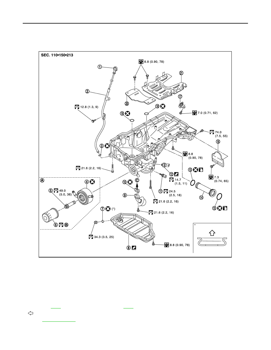
OIL PAN (UPPER)
OIL PAN (UPPER)
Exploded View
INFOID:0000000005245247
1.
Oil level gauge
2.
Oil level gauge guide
3.
O-ring
4.
Oil cooler
5.
Connector bolt
6.
Oil filter
7.
Drain plug washer
8.
Oil pan (lower)
9.
Oil strainer
10. Gasket
11.
Oil temperature sensor
12. Oil pressure switch
13. O-ring
14. Axle pipe
15. O-ring
16. Rear plate cover
17. Crankshaft position sensor (POS)
18. O-ring
19. O-ring
20. Baffle plate
21. Baffle plate
A.
Refer to
B.
Refer to
C.
Oil pump side
: Oil pan side
for symbols in the figure.
JPBIA2088GB