Infiniti FX35, FX50 (S51). Manual - part 937
EM-48
< REMOVAL AND INSTALLATION >
[VQ35HR]
OIL PAN (LOWER) AND OIL STRAINER
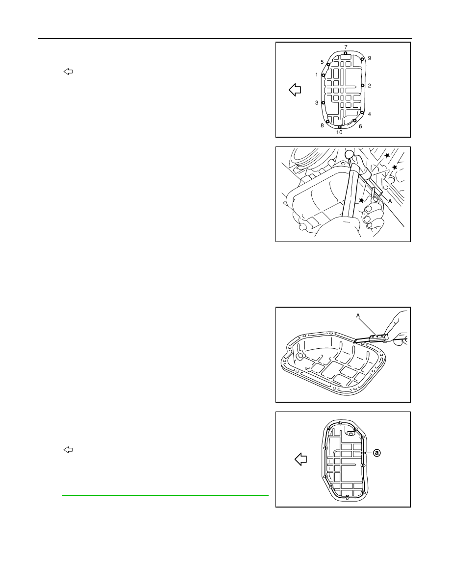
a.
Loosen mounting bolts in reverse order as shown in the figure to
remove.
b.
Insert the seal cutter [SST: KV10111100 (J-37228)] (A) between
oil pan (upper) and oil pan (lower).
CAUTION:
• Be careful not to damage the mating surfaces.
• Never insert a screwdriver, this will damage the mating
surfaces.
c.
Slide the seal cutter by tapping on the side of tool with a ham-
mer. Remove oil pan (lower).
4.
Remove oil strainer.
INSTALLATION
1.
Install oil strainer.
2.
Install oil pan (lower) as per the following:
a.
Use scraper (A) to remove old liquid gasket from mating sur-
faces.
• Remove old liquid gasket from the bolt holes and thread.
CAUTION:
Never scratch or damage the mating surfaces when clean-
ing off old liquid gasket.
b.
Apply a continuous bead of liquid gasket with the tube presser
(commercial service tool) to the oil pan (lower) as shown in the
figure.
Use Genuine RTV Silicone Sealant or an equivalent. Refer
to
GI-16, "Recommended Chemical Products and Sealants"
.
CAUTION:
Attaching must be done within 5 minutes after coating.
c.
Install oil pan (lower).
: Engine front
JPBIA0021ZZ
JPBIA0276ZZ
JPBIA0025ZZ
: Engine front
a
:
φ
4.0 - 5.0 mm (0.157 - 0.197 in)
JPBIA1556ZZ