Infiniti FX35, FX50 (S51). Manual - part 935
EM-40
< REMOVAL AND INSTALLATION >
[VQ35HR]
FUEL INJECTOR AND FUEL TUBE
FUEL INJECTOR AND FUEL TUBE
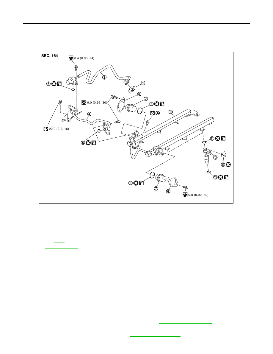
Exploded View
INFOID:0000000005245138
CAUTION:
Never remove or disassemble parts unless instructed as shown in the figure.
Removal and Installation
INFOID:0000000005245139
REMOVAL
WARNING:
• Put a “CAUTION: FLAMMABLE” sign in the workshop.
• Be sure to work in a well ventilated area and furnish workshop with a CO
2
fire extinguisher.
• Never smoke while servicing fuel system. Keep open flames and sparks away from the work area.
• Never drain engine coolant when the engine is hot to avoid the danger of being scalded.
1.
Release fuel pressure. Refer to
.
2.
Disconnect battery cable from the negative terminal. Refer to
.
3.
Remove engine cover with power tool. Refer to
.
4.
Remove air cleaner case and air duct. Refer to
1.
Quick connector cap
2.
Fuel feed hose (with damper)
3.
O-ring
4.
Fuel sub tube
5.
O-ring
6.
Fuel damper cap
7.
Fuel damper
8.
O-ring
9.
Fuel tube
10. Clip
11. O-ring (black)
12. Fuel injector
13. O-ring (green)
A.
Refer to
Refer to
for symbols in the figure.
JPBIA1708GB