Infiniti FX35, FX50 (S51). Manual - part 933
EM-32
< REMOVAL AND INSTALLATION >
[VQ35HR]
INTAKE MANIFOLD COLLECTOR
CAUTION:
• Perform this step when engine is cold.
• Never spill engine coolant on drive belt.
b.
Disconnect water hoses from electric throttle control actuator. When engine coolant is not drained from
radiator, attach plug to water hoses to prevent engine coolant leakage.
c.
Disconnect harness connector.
d.
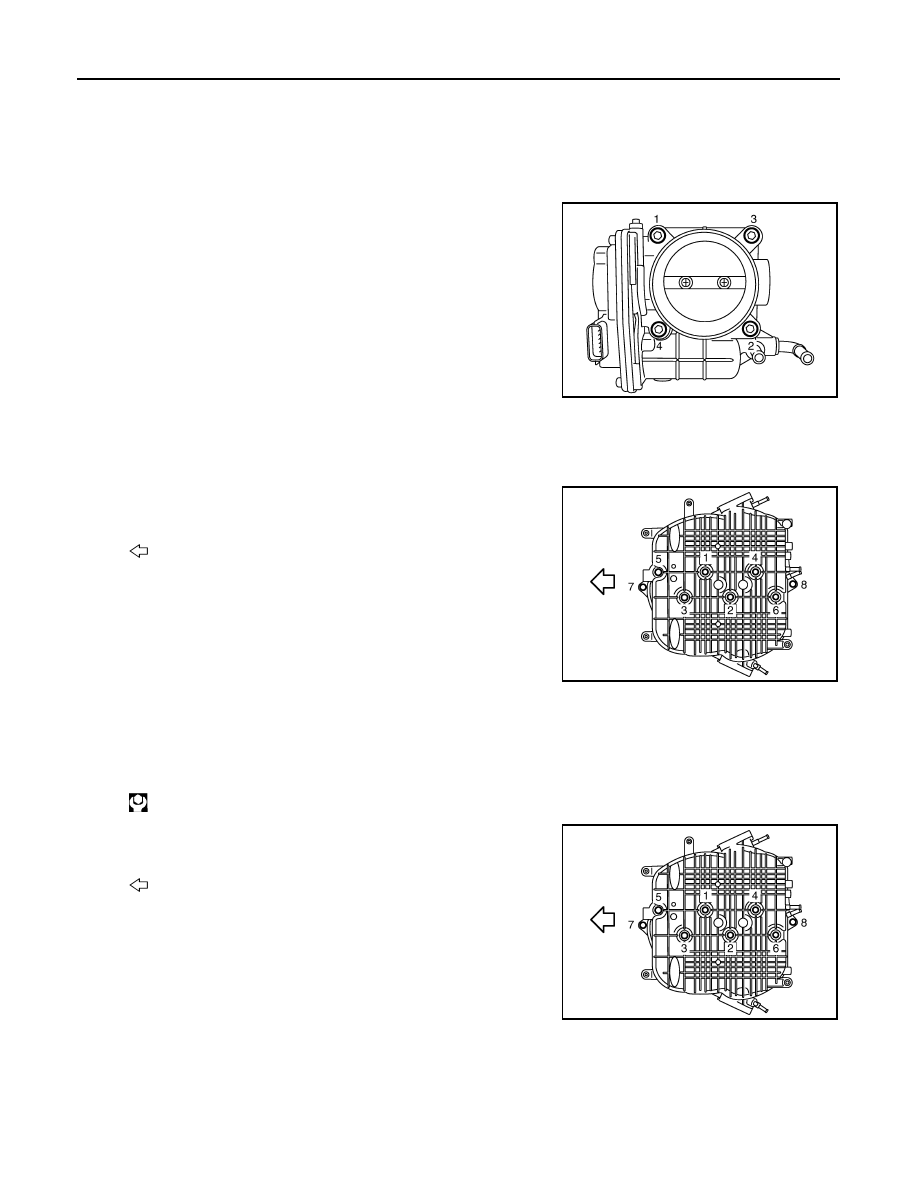
Loosen mounting bolts in reverse order as shown in the figure.
NOTE:
• When removing only intake manifold collector, move electric
throttle control actuator without disconnecting the water hose.
• The figure shows the electric throttle control actuator (bank 1)
viewed from the air duct side.
• Viewed from the air duct side, order of loosening mounting
bolts of electric throttle control actuator (bank 2) is the same
as that of the electric throttle control actuator (bank 1).
CAUTION:
Handle carefully to avoid any impact to electric throttle con-
trol actuator.
4.
Disconnect vacuum hose, PCV hose and EVAP hose from intake manifold collector.
5.
Remove EVAP canister purge volume control solenoid valve and EVAP tube assembly from intake mani-
fold collector.
6.
Loosen mounting bolts and nuts with power tool in the reverse
order as shown in the figure to remove intake manifold collector.
INSTALLATION
Note the following item, and install in the reverse order of removal.
INTAKE MANIFOLD COLLECTOR
• If stud bolts were removed, install them and tighten to the specified torque below.
• Tighten mounting bolts and nuts in numerical order as shown in the
figure.
WATER HOSE
• Insert hose by 27 to 32 mm (1.06 to 1.26 in) from connector end.
• Clamp hose at location of 3 to 7 mm (0.12 to 0.28 in) from hose end.
ELECTRIC THROTTLE CONTROL ACTUATOR (BANK 1 AND BANK 2)
JPBIA0011ZZ
: Engine front
JPBIA0012ZZ
: 10.8 N·m (1.1 kg-m, 8 ft-lb)
: Engine front
JPBIA0012ZZ