Infiniti FX35, FX50 (S51). Manual - part 911
ECM
EC-1185
< ECU DIAGNOSIS INFORMATION >
[VK50VE]
C
D
E
F
G
H
I
J
K
L
M
A
EC
N
P
O
WITH CONSULT-III
Perform corresponding DTC Confirmation Procedure one by one based on Performance Priority in the table
on “SRT Item”.
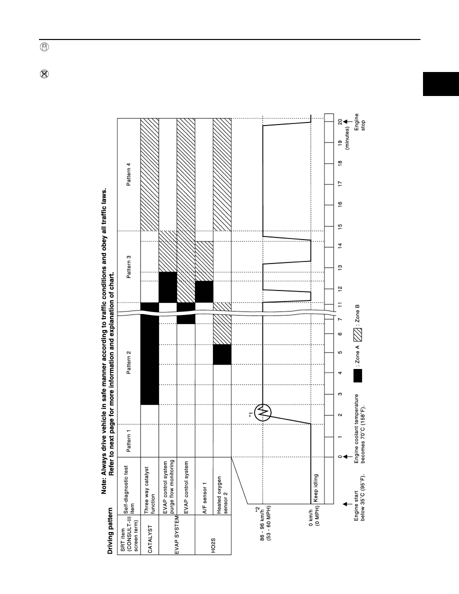
WITHOUT CONSULT-III
The most efficient driving pattern in which SRT codes can be properly set is explained below. The driving pat-
tern should be performed one or more times to set all SRT codes.
DRIVING PATTERN
PBIB3622E