Infiniti FX35, FX50 (S51). Manual - part 899
ECM
EC-1137
< ECU DIAGNOSIS INFORMATION >
[VK50VE]
C
D
E
F
G
H
I
J
K
L
M
A
EC
N
P
O
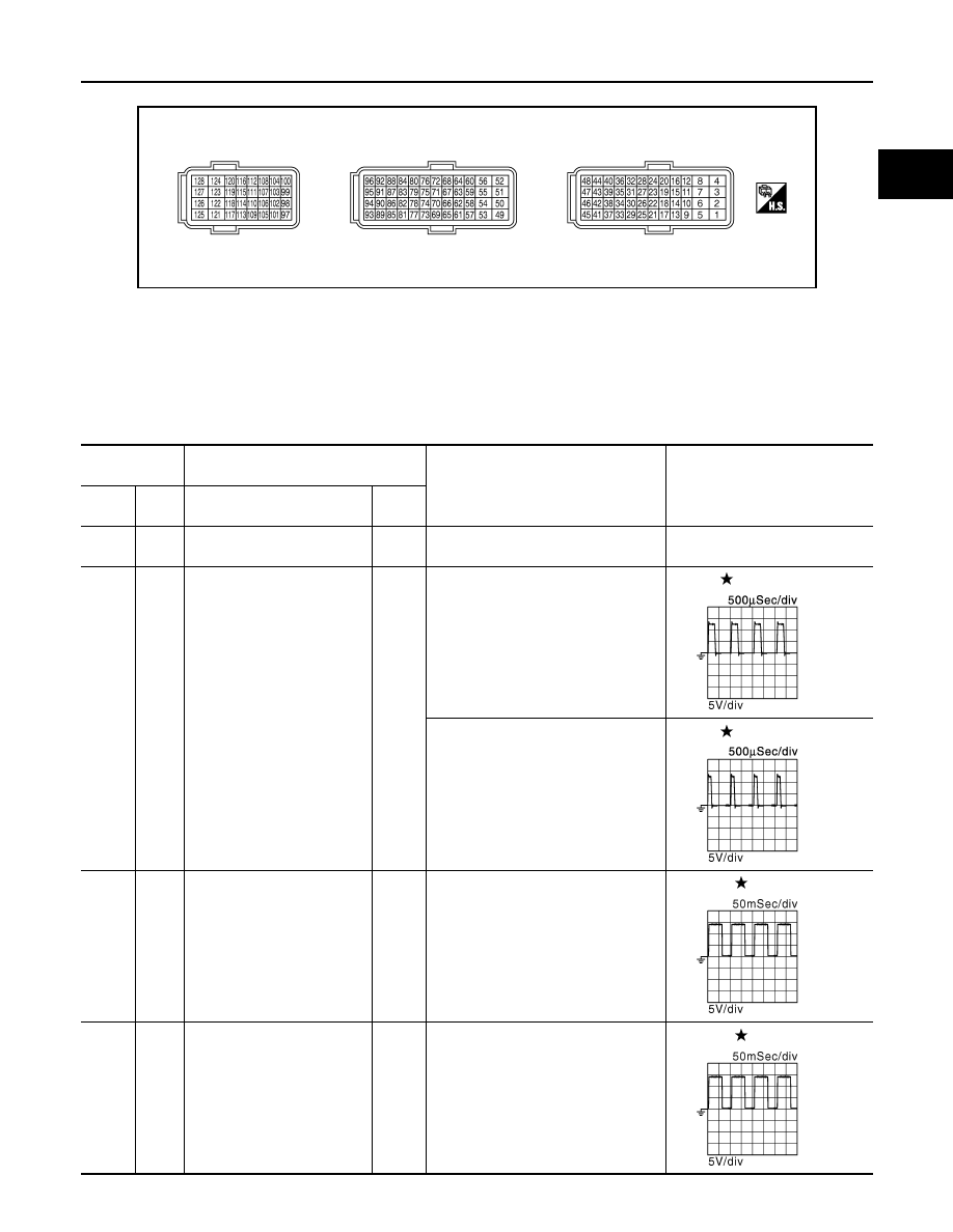
TERMINAL LAYOUT
PHYSICAL VALUES
NOTE:
• ECM is located behind the instrument assist lower panel. For this inspection, remove passenger side instru-
ment lower panel.
• Specification data are reference values and are measured between each terminals.
• Pulse signal is measured by CONSULT-III.
JMBIA0070ZZ
Terminal No.
(Wire color)
Description
Condition
Value
(Approx.)
+
–
Signal name
Input/
Output
1
(P)
128
(B)
Throttle control motor power
supply (bank 2)
Input
[Ignition switch: ON]
BATTERY VOLTAGE
(11 - 14 V)
2
(L)
128
(B)
Throttle control motor (bank 2)
(Open)
Output
[Ignition switch: ON]
• Engine: Stopped
• Selector lever: D position
• Accelerator pedal: Fully depressed
0 - 14 V
[Ignition switch: ON]
• Engine: Stopped
• Selector lever: D position
• Accelerator pedal: Fully released
0 - 14 V
3
(Y)
128
(B)
A/F sensor 1 heater
(bank 1)
Output
[Engine is running]
• Warm-up condition
• Idle speed
(More than 140 seconds after start-
ing engine)
2.9 - 8.8 V
4
(G)
128
(B)
A/F sensor 1 heater
(bank 2)
Output
[Engine is running]
• Warm-up condition
• Idle speed
(More than 140 seconds after start-
ing engine)
2.9 - 8.8 V
JMBIA0031GB
JMBIA0032GB
JMBIA0030GB
JMBIA0030GB