Infiniti FX35, FX50 (S51). Manual - part 894


  Index      Infiniti     Infiniti FX35, FX50 (S51) - service repair manual 2010 year


Search            


Content   ..  892  893  894  895   ..


Infiniti FX35, FX50 (S51). Manual - part 894


IGNITION SIGNAL

EC-1117

< DTC/CIRCUIT DIAGNOSIS >

[VK50VE]

C

D

E

F

G

H

I

J

K

L

M

A

EC

N

P

O

NO

>> Repair open circuit or short to power in harness or connectors.

10.

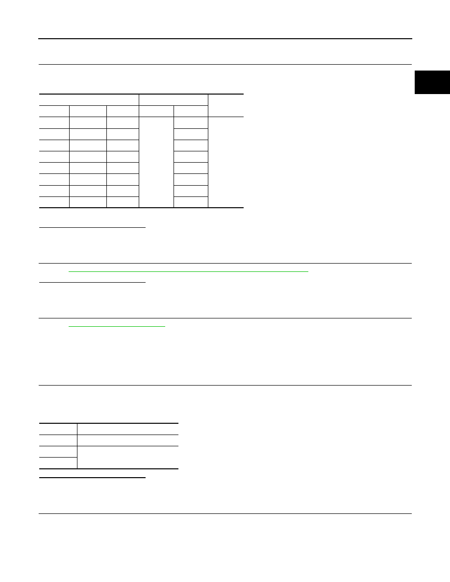
CHECK IGNITION COIL OUTPUT SIGNAL CIRCUIT FOR OPEN AND SHORT

1.

Disconnect ECM harness connector.

2.

Check the continuity between ignition coil harness connector and ECM harness connector.

3.

Also check harness for short to ground and short to power.

Is the inspection result normal?

YES

>> GO TO 11.

NO

>> Repair open circuit, short to ground or short to power in harness or connectors.

11.

CHECK IGNITION COIL WITH POWER TRANSISTOR

Refer to 

EC-1117, "Component Inspection (Ignition Coil with Power Transistor)"

.

Is the inspection result normal?

YES

>> GO TO 12.

NO

>> Replace malfunctioning ignition coil with power transistor.

12.

CHECK INTERMITTENT INCIDENT

Refer to 

GI-36, "Intermittent Incident"

.

>> INSPECTION END

Component Inspection (Ignition Coil with Power Transistor)

INFOID:0000000005237623

1.

CHECK IGNITION COIL WITH POWER TRANSISTOR-I

1.

Turn ignition switch OFF.

2.

Disconnect ignition coil harness connector.

3.

Check resistance between ignition coil terminals as per the following.

Is the inspection result normal?

YES

>> GO TO 2.

NO

>> Replace malfunctioning ignition coil with power transistor.

2.

CHECK IGNITION COIL WITH POWER TRANSISTOR-II

CAUTION:

Perform the following procedure in a place with no combustible objects and good ventilation.
1.

Turn ignition switch OFF.

2.

Reconnect all harness connectors disconnected.

Ignition coil

ECM

Continuity

Cylinder

Connector

Terminal

Connector

Terminal

1

F75

1

F110

10

Existed

2

F76

1

9

3

F77

1

13

4

F78

1

14

5

F79

1

18

6

F80

1

22

7

F81

1

28

8

F82

1

30

Terminals

Resistance [at 25

°

C (77

°

F)]

1 and 2

Except 0 or 


1 and 3

Except 0 

2 and 3

EC-1118

< DTC/CIRCUIT DIAGNOSIS >

[VK50VE]

IGNITION SIGNAL

3.

Remove fuel pump fuse (1) in IPDM E/R (2) to release fuel pres-
sure.
NOTE:
Do not use CONSULT-III to release fuel pressure, or fuel pres-
sure applies again during the following procedure.

4.

Start engine.

5.

After engine stalls, crank it 2 or 3 times to release all fuel pres-
sure.

6.

Turn ignition switch OFF.

7.

Remove all ignition coil harness connectors to avoid the electri-
cal discharge from the ignition coils.

8.

Remove ignition coil and spark plug of the cylinder to be
checked.

9.

Crank engine for 5 seconds or more to remove combustion gas in the cylinder.

10. Connect spark plug and harness connector to ignition coil.
11. Fix ignition coil using a rope etc. with gap of 13 - 17 mm (0.52 -

0.66 in) between the edge of the spark plug and grounded metal
portion as shown in the figure.

12. Crank engine for approximately 3 seconds, and check whether

spark is generated between the spark plug and the grounded
metal portion.

CAUTION:

• Never place the spark plug and the ignition coil within 50

cm (19.7 in) each other. Be careful not to get an electrical
shock while checking, because the electrical discharge
voltage becomes 20 kV or more.

• It might damage the ignition coil if the gap of more than 17 mm (0.66 in) is made.
NOTE:
When the gap is less than 13 mm (0.52 in), a spark might be generated even if the coil is malfunc-
tioning.

Is the inspection result normal?

YES

>> INSPECTION END

NO

>> Replace malfunctioning ignition coil with power transistor.

Component Inspection (Condenser)

INFOID:0000000005237624

1.

CHECK CONDENSER

1.

Turn ignition switch OFF.

2.

Disconnect condenser harness connector.

3.

Check resistance between condenser terminals as per the following.

Is the inspection result normal?

YES

>> INSPECTION END

NO

>> Replace condenser.

Spark should be generated.

JMBIA1552ZZ

JMBIA0066GB

Terminals

Resistance

1 and 2

Above 1 M

 [at 25

°

C (77

°

F)]

INFORMATION DISPLAY (ASCD)

EC-1119

< DTC/CIRCUIT DIAGNOSIS >

[VK50VE]

C

D

E

F

G

H

I

J

K

L

M

A

EC

N

P

O

INFORMATION DISPLAY (ASCD)

Description

INFOID:0000000005237625

The operation mode of the ASCD is indicated on the information display in the combination meter. When turn-
ing ON the MAIN switch of the ASCD steering switch, the CRUISE lamp turns ON, CRUISE is indicated on the
information display and the operation mode turns to standby mode. When turning ON the SET/COAST switch
while the vehicle is driven at the ASCD setting condition speed range, the SET lamp turns ON and the set
speed is indicated on the information display. When the canceling conditions come into effect, CANCEL is indi-
cated on the information display.

Component Function Check

INFOID:0000000005237626

1.

CHECK INFORMATION DISPLAY

1.

Start engine.

2.

Press MAIN switch on ASCD steering switch.

3.

Drive the vehicle at more than 40 km/h (25 MPH).

CAUTION:

Always drive vehicle at a safe speed.

4.

Press SET/COAST switch.

5.

Check that the reading of the speedometer shows the same value as the set speed indicated in the infor-
mation display while driving the vehicle on a flat road.

Is the inspection result normal?

YES

>> INSPECTION END

NO

>> Go to 

EC-1119, "Diagnosis Procedure"

.

Diagnosis Procedure

INFOID:0000000005237627

1.

CHECK DTC

Check that DTC UXXXX, P0500 or P1574 is not displayed.

Is the inspection result normal?

YES

>> GO TO 2.

NO-1

>> Perform trouble diagnosis for DTC UXXXX.

NO-2

>> Perform trouble diagnosis for DTC P0500. Refer to 

EC-948, "DTC Logic"

.

NO-3

>> Perform trouble diagnosis for DTC P1574. Refer to 

EC-1059, "DTC Logic"

 (Without ICC) or 

EC-

1061, "DTC Logic"

 (With ICC).

2.

CHECK DTC WITH “UNIFIED METER & A/C AMP.”

Refer to 

MWI-45, "CONSULT-III Function (METER/M&A)"

.

Is the inspection result normal?

YES

>> GO TO 3.

NO

>> Perform trouble diagnosis for DTC indicated.

3.

CHECK INTERMITTENT INCIDENT

Refer to 

GI-36, "Intermittent Incident"

.

Is the inspection result normal?

YES

>> Replace combination meter.

NO

>> Repair or replace.

EC-1120

< DTC/CIRCUIT DIAGNOSIS >

[VK50VE]

MALFUNCTION INDICATOR LAMP

MALFUNCTION INDICATOR LAMP

Description

INFOID:0000000005237628

The Malfunction Indicator Lamp (MIL) is located on the combination
meter.
The MIL will illuminate when the ignition switch is turned ON without
the engine running. This is a bulb check.
When the engine is started, the MIL should turn off. If the MIL
remains illuminated, the on board diagnostic system has detected an
engine system malfunction.
For details, refer to 

EC-705, "Diagnosis Description"

.

Component Function Check

INFOID:0000000005237629

1.

CHECK MIL FUNCTION

1.

Turn ignition switch ON.

2.

Check that MIL illuminates.

Is the inspection result normal?

YES

>> INSPECTION END

NO

>> Go to 

EC-1120, "Diagnosis Procedure"

.

Diagnosis Procedure

INFOID:0000000005237630

1.

CHECK DTC

Check that DTC UXXXX is not displayed.

Is the inspection result normal?

YES

>> GO TO 2.

NO

>> Perform trouble diagnosis for DTC UXXXX.

2.

CHECK DTC WITH “UNIFIED METER AND A/C AMP.”

Refer to 

MWI-45, "CONSULT-III Function (METER/M&A)"

.

Is the inspection result normal?

YES

>> GO TO 3.

NO

>> Perform trouble diagnosis for DTC indicated.

3.

CHECK INTERMITTENT INCIDENT

Refer to 

GI-36, "Intermittent Incident"

.

Is the inspection result normal?

YES

>> Replace combination meter.

NO

>> Repair or replace malfunctioning part.

SEF217U


Content   ..  892  893  894  895   ..