Infiniti FX35, FX50 (S51). Manual - part 866
P1226, P1235 TP SENSOR
EC-1005
< DTC/CIRCUIT DIAGNOSIS >
[VK50VE]
C
D
E
F
G
H
I
J
K
L
M
A
EC
N
P
O
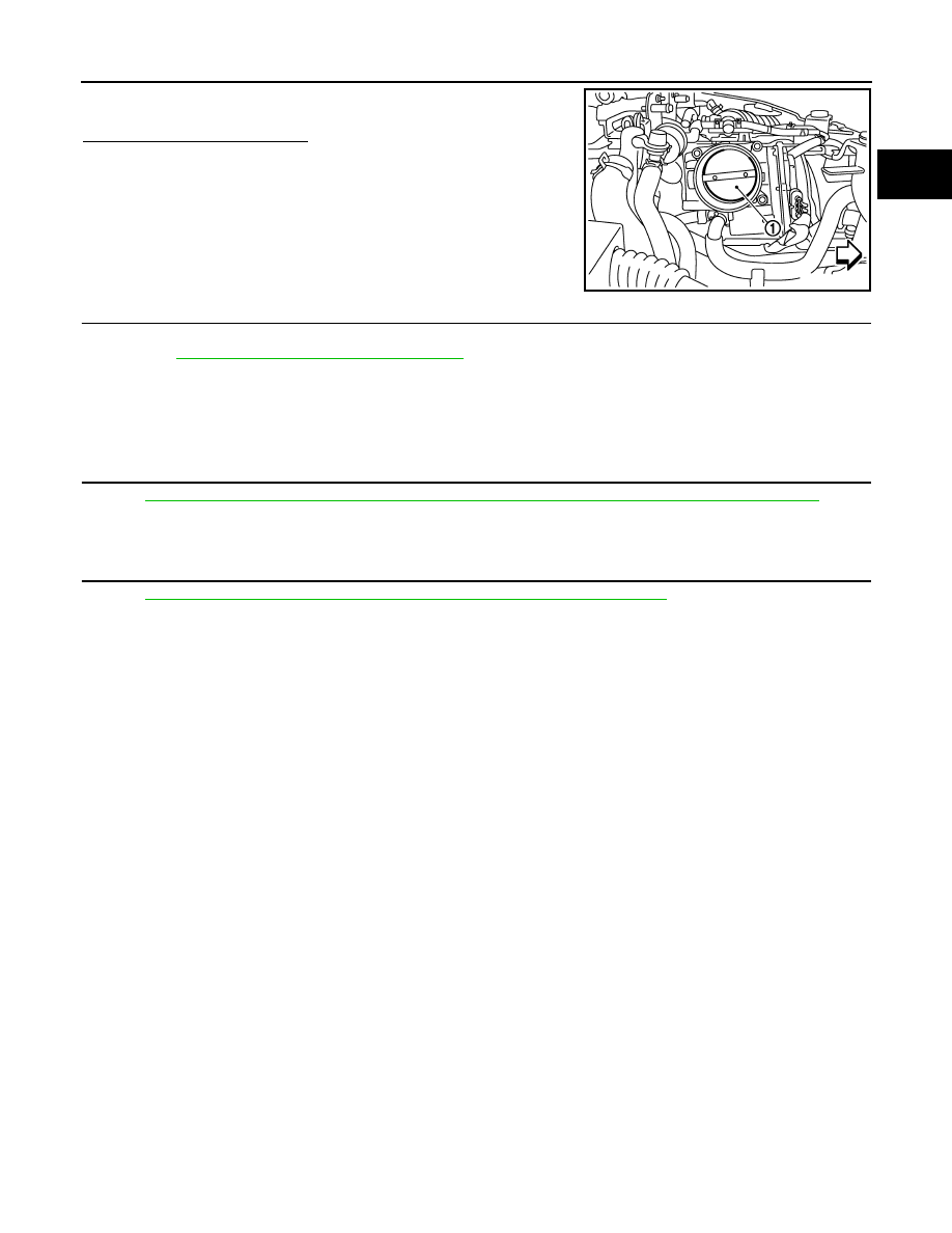
3.
Check that no foreign matter is caught between the throttle valve
(1) and the housing.
Is the inspection result normal?
YES
>> GO TO 2.
NO
>> Remove the foreign matter and clean the electric throttle
control actuator inside.
2.
REPLACE ELECTRIC THROTTLE CONTROL ACTUATOR
1.
Replace malfunctioning electric throttle control actuator.
2.
EC-1005, "Special Repair Requirement"
.
>> INSPECTION END
Special Repair Requirement
INFOID:0000000005237489
1.
PERFORM THROTTLE VALVE CLOSED POSITION LEARNING
EC-581, "THROTTLE VALVE CLOSED POSITION LEARNING : Special Repair Requirement"
>> GO TO 2.
2.
PERFORM IDLE AIR VOLUME LEARNING
EC-582, "IDLE AIR VOLUME LEARNING : Special Repair Requirement"
>> END
JMBIA1556ZZ