Infiniti FX35, FX50 (S51). Manual - part 857


  Index      Infiniti     Infiniti FX35, FX50 (S51) - service repair manual 2010 year


Search            


Content   ..  855  856  857  858   ..


Infiniti FX35, FX50 (S51). Manual - part 857


P0850 PNP SWITCH

EC-969

< DTC/CIRCUIT DIAGNOSIS >

[VK50VE]

C

D

E

F

G

H

I

J

K

L

M

A

EC

N

P

O

4.

Check 1st trip DTC.

Is 1st trip DTC detected?

YES

>> Go to 

EC-969, "Diagnosis Procedure"

.

NO

>> INSPECTION END

5.

PERFORM COMPONENT FUNCTION CHECK

 With GST

Perform Component Function Check. Refer to 

EC-969, "Component Function Check"

.

NOTE:
Use Component Function Check to check the overall function of the park/neutral position (PNP) signal circuit.
During this check, a 1st trip DTC might not be confirmed.

Is the inspection result normal?

YES

>> INSPECTION END

NO

>> Go to 

EC-969, "Diagnosis Procedure"

.

Component Function Check

INFOID:0000000005237442

1.

PERFORM COMPONENT FUNCTION CHECK

 With GST

1.

Turn ignition switch ON.

2.

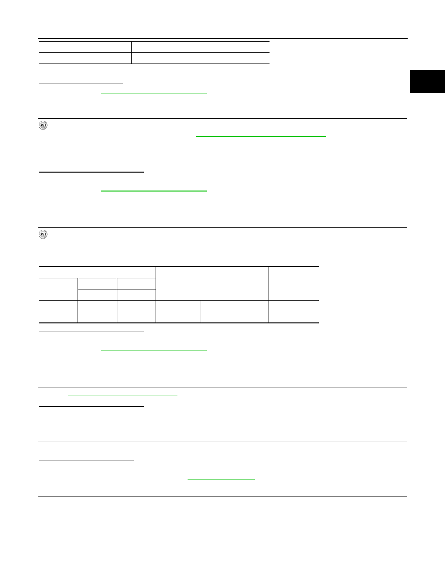
Check the voltage between ECM harness connector terminals under the following conditions.

Is the inspection result normal?

YES

>> INSPECTION END

NO

>> Go to 

EC-969, "Diagnosis Procedure"

.

Diagnosis Procedure

INFOID:0000000005237443

1.

CHECK DTC WITH TCM

Refer to 

TM-242, "Diagnosis Description"

.

Is the inspection result normal?

YES

>> GO TO 2.

NO

>> Repair or replace malfunctioning part.

2.

CHECK STARTING SYSTEM

Turn ignition switch OFF, then turn it to START.

Does starter motor operate?

YES

>> GO TO 3.

NO

>> Check DTC with BCM. Refer to 

STR-2, "Work Flow"

.

3.

CHECK PNP SIGNAL CIRCUIT FOR OPEN AND SHORT

1.

Turn ignition switch OFF.

2.

Disconnect A/T assembly harness connector.

3.

Disconnect ECM harness connector.

4.

Check the continuity between A/T assembly harness connector and ECM harness connector.

VHCL SPEED SE

More than 64 km/h (40 mph)

Selector lever

Suitable position

ECM

Condition

Voltage (V)

Connector

+

Terminal

Terminal

M160

116

128

Selector lever

P or N position

Battery voltage

Except above position

Approx. 0

EC-970

< DTC/CIRCUIT DIAGNOSIS >

[VK50VE]

P0850 PNP SWITCH

5.

Also check harness for short to ground and short to power.

Is the inspection result normal?

YES

>> GO TO 5.

NO

>> GO TO 4.

4.

DETECT MALFUNCTIONING PART

Check the following.
• Harness connectors F10, E10
• Harness connectors E106, M6
• Harness for open or short between A/T assembly and ECM

>> Repair open circuit, short to ground or short to power in harness or connectors.

5.

CHECK INTERMITTENT INCIDENT

Refer to 

GI-36, "Intermittent Incident"

.

>> INSPECTION END

A/T assembly

ECM

Continuity

Connector

Terminal

Connector

Terminal

F51

9

M160

116

Existed

P100A, P100B VVEL SYSTEM

EC-971

< DTC/CIRCUIT DIAGNOSIS >

[VK50VE]

C

D

E

F

G

H

I

J

K

L

M

A

EC

N

P

O

P100A, P100B VVEL SYSTEM

DTC Logic

INFOID:0000000005237444

DTC DETECTION LOGIC

NOTE:
If DTC P100A or P100B is displayed with DTC P1090 or P1093, first perform the trouble diagnosis for DTC
P1090 or P1093. Refer to 

EC-989, "DTC Logic"

.

DTC CONFIRMATION PROCEDURE

1.

PRECONDITIONING 

If DTC Confirmation Procedure has been previously conducted, always perform the following procedure
before conducting the next test. 
1.

Turn ignition switch OFF and wait at least 10 seconds.

2.

Turn ignition switch ON.

3.

Turn ignition switch OFF and wait at least 10 seconds.

TESTING CONDITION:
Before performing the following procedure, confirm that battery voltage is more than 10 V at idle.

>> GO TO 2.

2.

PERFORM DTC CONFIRMATION PROCEDURE

1.

Start engine.

2.

Depress the accelerator pedal rapidly half or more under no load conditions, and then release it.

3.

Wait at idle for 5 seconds or more.

4.

Repeat steps 2 to 3 for three times.

5.

Check 1st trip DTC.

Is DTC detected?

YES

>> Go to 

EC-971, "Diagnosis Procedure"

.

NO

>> INSPECTION END

Diagnosis Procedure

INFOID:0000000005237445

1.

CHECK GROUND CONNECTION

1.

Turn ignition switch OFF.

2.

Check ground connection M95. Refer to Ground Inspection in 

GI-39, "Circuit Inspection"

.

Is the inspection result normal?

YES

>> GO TO 2.

NO

>> Repair or replace ground connection.

2.

VVEL ACTUATOR MOTOR OUTPUT SIGNAL CIRCUIT FOR OPEN AND SHORT

1.

Disconnect VVEL control module harness connector.

2.

Disconnect VVEL actuator motor harness connector.

3.

Check the continuity between VVEL control module harness connector and VVEL actuator motor harness
connector.

DTC No.

Trouble diagnosis name

DTC detecting condition

Possible cause

P100A

VVEL response malfunction 
(bank 1)

Actual event response to target is 
poor.

• Harness or connectors

(VVEL actuator motor circuit is open or shorted.)

• VVEL actuator motor
• VVEL actuator sub assembly
• VVEL ladder assembly
• VVEL control module

P100B

VVEL response malfunction 
(bank 2)

EC-972

< DTC/CIRCUIT DIAGNOSIS >

[VK50VE]

P100A, P100B VVEL SYSTEM

4.

Also check harness for short to ground and power.

Is the inspection result normal?

YES

>> GO TO 4.

NO

>> GO TO 3.

3.

DETECT MALFUNCTIONING PART

Check the following.
• Harness connectors F10, E10
• Harness for open or short between VVEL actuator motor and VVEL control module

>> Repair open circuit, short to ground or short to power in harness or connectors.

4.

CHECK VVEL ACTUATOR MOTOR

Refer to 

EC-973, "Component Inspection (VVEL ACTUATOR MOTOR)"

.

Is the inspection result normal?

YES

>> GO TO 6.

NO

>> GO TO 5.

5.

REPLACE VVEL ACTUATOR SUB ASSEMBLY

1.

Replace VVEL actuator sub assembly.

2.

Perform 

EC-974, "Special Repair Requirement"

.

>> INSPECTION END

6.

CHECK INTERMITTENT INCIDENT

Refer to 

GI-36, "Intermittent Incident"

.

Is the inspection result normal?

YES

>> GO TO 7.

NO

>> Repair or replace.

7.

REPLACE VVEL CONTROL MODULE

1.

Replace VVEL control module.

2.

Go to 

EC-579, "ADDITIONAL SERVICE WHEN REPLACING CONTROL UNIT (VVEL CONTROL MOD-

ULE) : Special Repair Requirement"

.

>> GO TO 8.

8.

PERFORM DTC CONFIRMATION PROCEDURE

1.

Turn ignition switch ON.

2.

Erase 1st trip DTC.

3.

Perform DTC Confirmation Procedure.
See 

EC-971, "DTC Logic"

.

Is the DTC P100A or P100B displayed again?

DTC No.

VVEL control module

VVEL actuator motor

Continuity

Bank

Connector

Terminal

Connector

Terminal

P100A

1

E15

12

F73

1

Existed

2

Not existed

25

1

Not existed

2

Existed

P100B

2

2

F71

1

Existed

2

Not existed

15

1

Not existed

2

Existed


Content   ..  855  856  857  858   ..