Infiniti FX35, FX50 (S51). Manual - part 830
P0222, P0223, P2132, P2133 TP SENSOR
EC-861
< DTC/CIRCUIT DIAGNOSIS >
[VK50VE]
C
D
E
F
G
H
I
J
K
L
M
A
EC
N
P
O
Is the inspection result normal?
YES
>> GO TO 2.
NO
>> Repair or replace ground connection.
2.
CHECK THROTTLE POSITION SENSOR 1 POWER SUPPLY CIRCUIT-I
1.
Disconnect electric throttle control actuator harness connector.
2.
Turn ignition switch ON.
3.
Check the voltage between electric throttle control actuator harness connector and ground.
Is the inspection result normal?
YES
>> GO TO 3.
NO
>> Repair open circuit, short to ground or short to power in harness or connectors.
3.
CHECK THROTTLE POSITION SENSOR 1 GROUND CIRCUIT FOR OPEN AND SHORT
1.
Turn ignition switch OFF.
2.
Disconnect ECM harness connector.
3.
Check the continuity between electric throttle control actuator harness connector and ECM harness con-
nector.
4.
Also check harness for short to ground and short to power.
Is the inspection result normal?
YES
>> GO TO 4.
NO
>> Repair open circuit, short to ground or short to power in harness or connectors.
4.
CHECK THROTTLE POSITION SENSOR 1 INPUT SIGNAL CIRCUIT FOR OPEN AND SHORT
1.
Check the continuity between electric throttle control actuator harness connector and ECM harness con-
nector.
2.
Also check harness for short to ground and short to power.
Is the inspection result normal?
YES
>> GO TO 5.
NO
>> Repair open circuit, short to ground or short to power in harness or connectors.
5.
CHECK THROTTLE POSITION SENSOR
EC-862, "Component Inspection"
Is the inspection result normal?
YES
>> GO TO 7.
NO
>> GO TO 6.
6.
REPLACE ELECTRIC THROTTLE CONTROL ACTUATOR
1.
Replace malfunctioning electric throttle control actuator.
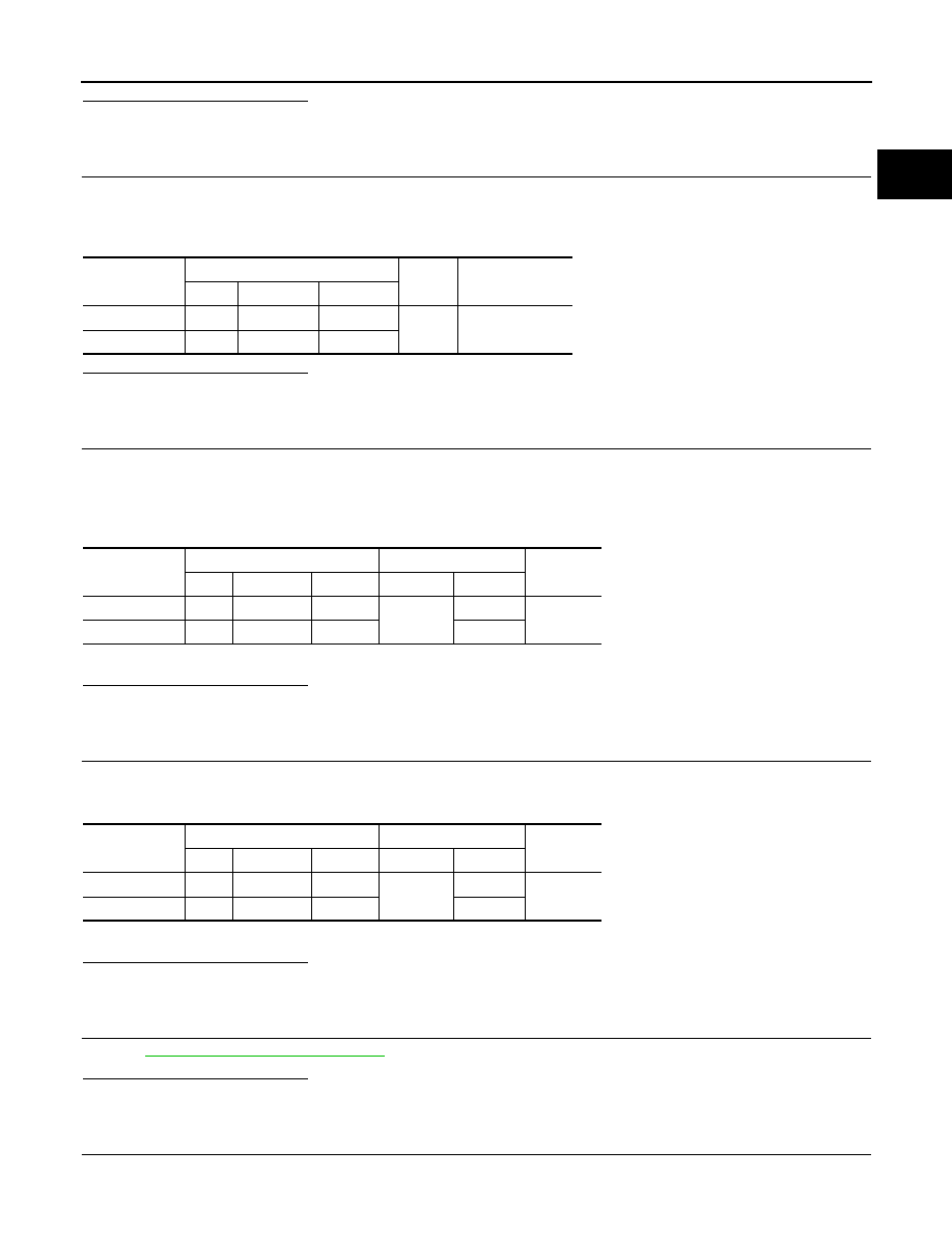
DTC
Electric throttle control actuator
Ground
Voltage (V)
Bank
Connector
Terminal
P0222, P0223
1
F66
2
Ground
Approx. 5
P2132, P2133
2
F64
2
DTC
Electric throttle control actuator
ECM
Continuity
Bank
Connector
Terminal
Connector
Terminal
P0222, P0223
1
F66
4
F111
71
Existed
P2132, P2133
2
F64
4
72
DTC
Electric throttle control actuator
ECM
Continuity
Bank
Connector
Terminal
Connector
Terminal
P0222, P0223
1
F66
4
F111
73
Existed
P2132, P2133
2
F64
2
77