Infiniti FX35, FX50 (S51). Manual - part 741


  Index      Infiniti     Infiniti FX35, FX50 (S51) - service repair manual 2010 year


Search            


Content   ..  739  740  741  742   ..


Infiniti FX35, FX50 (S51). Manual - part 741


ECM

EC-505

< ECU DIAGNOSIS INFORMATION >

[VQ35HR]

C

D

E

F

G

H

I

J

K

L

M

A

EC

N

P

O

7

(Y)

128

(B)

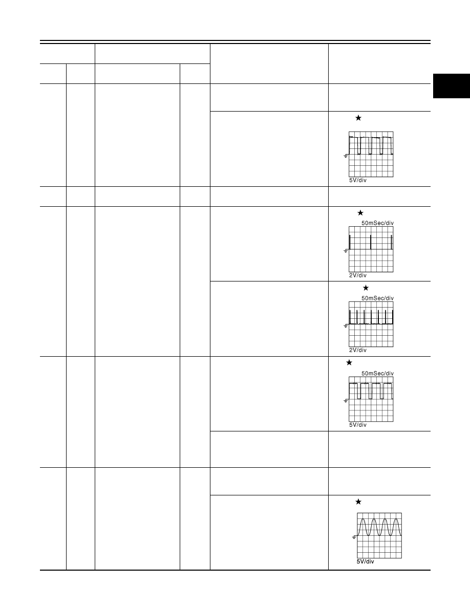
Exhaust valve timing con-
trol magnet retarder (bank 
2)

Output

[Engine is running]
• Warm-up condition
• Idle speed

BATTERY VOLTAGE
(11 - 14 V)

[Engine is running]
• Warm-up condition
• Around 2,500 rpm while the engine 

speed is rising

7 - 12 V

8

(B)

ECM ground

11

(GR)

128

(B)

Ignition signal No. 4

Output

[Engine is running]
• Warm-up condition
• Idle speed

NOTE:
The pulse cycle changes depending 
on rpm at idle

0 - 0.2 V

12

(L)

Ignition signal No. 3

15

(V)

Ignition signal No. 5

16

(G)

Ignition signal No. 2

[Engine is running]
• Warm-up condition
• Engine speed: 2,000 rpm

0.1 - 0.4 V

19

(SB)

Ignition signal No. 6

20

(Y)

Ignition signal No. 1

17

(P)

128

(B)

Heated oxygen sensor 2 
heater (bank 1)

Output

[Engine is running]
• Engine speed: Below 3,600 rpm after 

the following conditions are met

- Engine: after warming up
- Keeping the engine speed between 

3,500 and 4,000 rpm for 1 minute 
and at idle for 1 minute under no load

10 V

[Ignition switch: ON]
• Engine stopped
[Engine is running]
• Engine speed: Above 3,600 rpm

BATTERY VOLTAGE
(11 - 14 V)

18

(W)

128

(B)

Intake valve timing control 
solenoid valve (bank 1)

Output

[Engine is running]
• Warm-up condition
• Idle speed

BATTERY VOLTAGE
(11 - 14 V)

[Engine is running]
• Warm-up condition
• Engine speed: 2,000 rpm

7 - 12 V

Terminal No.

(Wire color)

Description

Condition

Value

(Approx.)

+

-–

Signal  name

Input/

Output

JMBIA0034GB

JMBIA0035GB

JMBIA0036GB

JMBIA0037GB

JMBIA1638GB

EC-506

< ECU DIAGNOSIS INFORMATION >

[VQ35HR]

ECM

21

(GR)

128

(B)

EVAP canister purge vol-
ume control solenoid valve

Output

[Engine is running]
• Idle speed
• Accelerator pedal: Not depressed 

even slightly, after engine starting

BATTERY VOLTAGE

(11 - 14 V)

[Engine is running]
• Engine speed: Approx. 2,000 rpm 

(More than 100 seconds after start-
ing engine)

BATTERY VOLTAGE

(11 - 14 V)

22

(LG)

128

(B)

Fuel pump relay

Output

[Ignition switch: ON]
• For 1 second after turning ignition 

switch ON

[Engine is running]

0 - 1.5 V

[Ignition switch: ON]
• More than 1 second after turning ig-

nition switch ON

BATTERY VOLTAGE
(11 - 14 V)

24

(BR)

128

(B)

ECM relay
(Self shut-off)

Output

[Engine is running]
[Ignition switch: OFF]
• A few seconds after turning ignition 

switch OFF

0 - 1.5 V

[Ignition switch: OFF]
• More than a few seconds after turn-

ing ignition switch OFF

BATTERY VOLTAGE
(11 - 14 V)

25

(O)

128

(B)

Throttle control motor relay

Output

[Ignition switch: ON 

 OFF]

0 - 1.0 V 

BATTERY VOLTAGE 
(11 - 14 V) 

0 V

[Ignition switch: ON]

0 - 1.0 V

29

(G)

128

(B)

Intake valve timing control 
solenoid valve (bank 2)

Output

[Engine is running]
• Warm-up condition
• Idle speed

BATTERY VOLTAGE
(11 - 14 V)

[Engine is running]
• Warm-up condition
• Engine speed: 2,000 rpm

7 - 12 V

Terminal No.

(Wire color)

Description

Condition

Value

(Approx.)

+

-–

Signal  name

Input/

Output

JMBIA0039GB

JMBIA0040GB

JMBIA1638GB

ECM

EC-507

< ECU DIAGNOSIS INFORMATION >

[VQ35HR]

C

D

E

F

G

H

I

J

K

L

M

A

EC

N

P

O

30

(Y)

40

(R)

Throttle position sensor 1 
(bank 1)

Input

[Ignition switch: ON]
• Engine stopped
• Selector lever: D
• Accelerator pedal: Fully released

More than 0.36 V

[Ignition switch: ON]
• Engine stopped
• Selector lever: D
• Accelerator pedal: Fully depressed

Less than 4.75 V

31

(R)

48

(W)

Throttle position sensor 1 
(bank 2)

Input

[Ignition switch: ON]
• Engine stopped
• Selector lever: D
• Accelerator pedal: Fully released

More than 0.36 V

[Ignition switch: ON]
• Engine stopped
• Selector lever: D
• Accelerator pedal: Fully depressed

Less than 4.75 V

33

(SB)

128

(B)

Heated oxygen sensor 2 
heater (bank 2)

Output

[Engine is running]
• Engine speed: Below 3,600 rpm after 

the following conditions are met

- Engine: after warming up
- Keeping the engine speed between 

3,500 and 4,000 rpm for 1 minute 
and at idle for 1 minute under no load

10 V

[Ignition switch: ON]
• Engine stopped
[Engine is running]
• Engine speed: Above 3,600 rpm

BATTERY VOLTAGE
(11 - 14 V)

34

(L)

40

(R)

Throttle position sensor 2 
(bank 1)

Input

[Ignition switch: ON]
• Engine stopped
• Selector lever: D
• Accelerator pedal: Fully released

Less than 4.75 V

[Ignition switch: ON]
• Engine stopped
• Selector lever: D
• Accelerator pedal: Fully depressed

More than 0.36 V

35

(B)

48

(W)

Throttle position sensor 2 
(bank 2)

Input

[Ignition switch: ON]
• Engine stopped
• Selector lever: D
• Accelerator pedal: Fully released

Less than 4.75 V

[Ignition switch: ON]
• Engine stopped
• Selector lever: D
• Accelerator pedal: Fully depressed

More than 0.36 V

Terminal No.

(Wire color)

Description

Condition

Value

(Approx.)

+

-–

Signal  name

Input/

Output

JMBIA0037GB

EC-508

< ECU DIAGNOSIS INFORMATION >

[VQ35HR]

ECM

37

(LG)

128

(B)

Crankshaft position sensor

Input

[Engine is running]
• Warm-up condition
• Idle speed

NOTE:
The pulse cycle changes depending 
on rpm at idle

4.0 - 5.0 V

[Engine is running]
• Engine speed: 2,000 rpm

4.0 - 5.0 V

40

(R)

Sensor ground
[Throttle position sensor 
(bank 1)]

43

(G)

48

(W)

Sensor power supply
[Throttle position sensor 
(bank 2)]

[Ignition switch: ON]

5 V

44

(B)

40

(R)

Sensor power supply
[Throttle position sensor 
(bank 1)]

[Ignition switch: ON]

5 V

46

(R)

47

(Y)

Sensor power supply
[Crankshaft position sen-
sor]

[Ignition switch: ON]

5 V

47

(Y)

Sensor ground
[Crankshaft position sen-
sor]

48

(W)

Sensor ground
[Throttle position sensor 
(bank 2)]

49

(L)

128

(B)

Throttle control motor 
(Close) (bank 2)

Output

[Ignition switch: ON]
• Engine stopped
• Selector lever: D
• Accelerator pedal: In the middle of 

releasing operation

0 - 14 V

Terminal No.

(Wire color)

Description

Condition

Value

(Approx.)

+

-–

Signal  name

Input/

Output

JMBIA0041GB

JMBIA0042GB

JMBIA0033GB


Content   ..  739  740  741  742   ..