Infiniti FX35, FX50 (S51). Manual - part 658
P0101, P010B MAF SENSOR
EC-173
< DTC/CIRCUIT DIAGNOSIS >
[VQ35HR]
C
D
E
F
G
H
I
J
K
L
M
A
EC
N
P
O
Is the inspection result normal?
YES
>> INSPECTION END.
NO
>> GO TO 2.
2.
CHECK FOR THE CAUSE OF UNEVEN AIR FLOW THROUGH MAF SENSOR
1.
Turn ignition switch OFF.
2.
Check for the cause of uneven air flow through MAF sensor. Refer to the following.
-
Crushed air ducts
-
Malfunctioning seal of air cleaner element
-
Uneven dirt of air cleaner element
-
Improper specification of intake air system parts
Is the inspection result normal?
YES
>> GO TO 4.
NO
>> GO TO 3.
3.
CHECK MAF SENSOR-II
With CONSULT-III
1.
Repair or replace malfunctioning part.
2.
Start engine and warm it up to normal operating temperature.
3.
Connect CONSULT-III and select “DATA MONITOR” mode.
4.
Select “MAS A/F SE-B1” and “MAS A/F SE-B2”, and check the indication.
*: Check for linear voltage rise in response to engine being increased to approximately 4,000 rpm.
Without CONSULT-III
1.
Repair or replace malfunctioning part.
2.
Start engine and warm it up to normal operating temperature.
3.
Check the voltage between ECM harness connector terminals under the following conditions.
*: Check for linear voltage rise in response to engine being increased to approximately 4,000 rpm.
Is the inspection result normal?
YES
>> INSPECTION END
NO
>> GO TO 4.
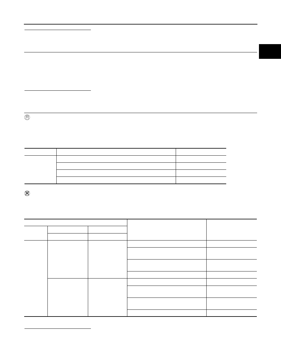
Monitor item
Condition
Indication (V)
MAS A/F SE-B1
MAS A/F SE-B2
Ignition switch ON (Engine stopped.)
Approx. 0.4
Idle (Engine is warmed-up to normal operating temperature.)
0.8 - 1.1
2,500 rpm (Engine is warmed-up to normal operating temperature.)
1.4 - 1.7
Idle to approx. 4,000 rpm
0.8 - 1.1 to approx. 2.4*
ECM
Condition
Voltage (V)
Connector
+
–
Terminal
Terminal
F102
77
[MAF sensor (bank 1)
signal]
68
Ignition switch ON (Engine stopped.)
Approx. 0.4
Idle (Engine is warmed-up to normal operat-
ing temperature.)
0.8 - 1.1
2,500 rpm (Engine is warmed-up to normal
operating temperature.)
1.4 - 1.7
Idle to approx. 4,000 rpm
0.8 - 1.1 to approx. 2.4*
79
[MAF sensor (bank 2)
signal]
94
Ignition switch ON (Engine stopped.)
Approx. 0.4
Idle (Engine is warmed-up to normal operat-
ing temperature.)
0.8 - 1.1
2,500 rpm (Engine is warmed-up to normal
operating temperature.)
1.4 - 1.7
Idle to approx. 4,000 rpm
0.8 - 1.1 to approx. 2.4*