Infiniti FX35, FX50 (S51). Manual - part 635
COOLING FAN CONTROL
EC-81
< SYSTEM DESCRIPTION >
[VQ35HR]
C
D
E
F
G
H
I
J
K
L
M
A
EC
N
P
O
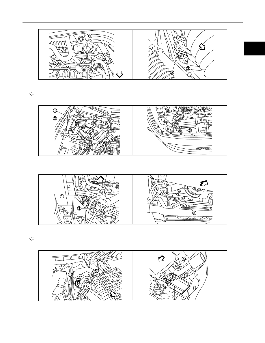
1.
Engine coolant temperature sensor
2.
A/F sensor 1 (bank 1)
3.
Crankshaft position sensor
: Vehicle front
1.
IPDM E/R
2.
Battery current sensor
3.
Refrigerant pressure sensor
1.
Power steering pressure sensor
2.
Alternator
3.
Engine oil temperature sensor
: Vehicle front
1.
EVAP service port
2.
EVAP canister purge volume control
solenoid valve
3.
EVAP canister vent control valve
JMBIA0011ZZ
JMBIA1501ZZ
JMBIA1502ZZ
JMBIA1503ZZ