Infiniti FX35, FX50 (S51). Manual - part 629


  Index      Infiniti     Infiniti FX35, FX50 (S51) - service repair manual 2010 year


Search            


Content   ..  627  628  629  630   ..


Infiniti FX35, FX50 (S51). Manual - part 629


ELECTRIC IGNITION SYSTEM

EC-57

< SYSTEM DESCRIPTION >

[VQ35HR]

C

D

E

F

G

H

I

J

K

L

M

A

EC

N

P

O

Component Description

INFOID:0000000005236705
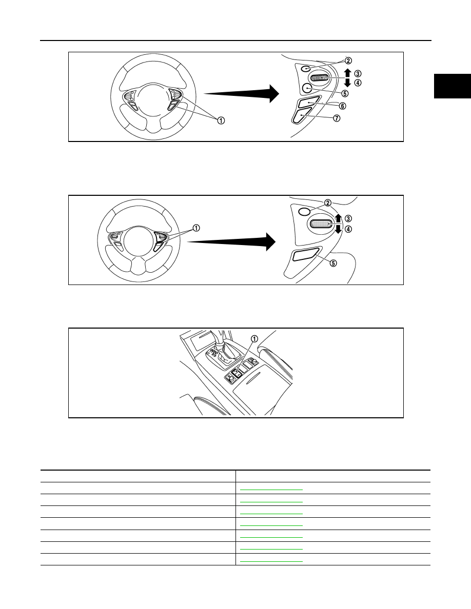
1.

ICC steering switch

2.

CANCEL switch

3.

RESUME/ACCELERATE switch

4.

SET/COAST switch

5.

DISTANCE switch

6.

MAIN switch

7.

LDP/DCA switch

1.

ASCD steering switch

2.

CANCEL switch

3.

RESUME/ACCELERATE switch

4.

SET/COAST switch

5.

MAIN switch

1.

Snow mode switch

JSBIA0155ZZ

JSBIA0156ZZ

JMBIA1623ZZ

Component

Reference

Accelerator pedal position sensor

EC-442, "Description"

Camshaft position sensor

EC-273, "Description"

Crankshaft position sensor

EC-268, "Description"

Engine coolant temperature sensor

EC-186, "Description"

Knock sensor

EC-265, "Description"

Mass air flow sensor

EC-168, "Description"

Throttle position sensor

EC-189, "Description"

EC-58

< SYSTEM DESCRIPTION >

[VQ35HR]

AIR CONDITIONING CUT CONTROL

AIR CONDITIONING CUT CONTROL

System Diagram

INFOID:0000000005236706

System Description

INFOID:0000000005236707

INPUT/OUTPUT SIGNAL CHART

*1: This signal is sent to the ECM via the CAN communication line.

*2: ECM determines the start signal status by the signals of engine speed and battery voltage.

SYSTEM DESCRIPTION

This system improves engine operation when the air conditioner is used.
Under the following conditions, the air conditioner is turned off.
• When the accelerator pedal is fully depressed.
• When cranking the engine.
• At high engine speeds.
• When the engine coolant temperature becomes excessively high.
• When operating power steering during low engine speed or low vehicle speed.
• When engine speed is excessively low.
• When refrigerant pressure is excessively low or high.

JMBIA1528GB

Sensor

Input Signal to ECM

ECM function

Actuator

Crankshaft position sensor

Engine speed*

2

Air conditioner 
cut control

IPDM E/R

A/C relay

Compressor

Camshaft position sensor

Engine coolant temperature sensor

Engine coolant temperature

Accelerator pedal position sensor

Accelerator pedal position

Battery

Battery voltage*

2

Refrigerant pressure sensor

Refrigerant pressure

Power steering pressure sensor

Power steering operation

Unified meter and A/C amp.

Vehicle speed & Air conditioner ON 

signal*

1

AIR CONDITIONING CUT CONTROL

EC-59

< SYSTEM DESCRIPTION >

[VQ35HR]

C

D

E

F

G

H

I

J

K

L

M

A

EC

N

P

O

Component Parts Location

INFOID:0000000005568462

1.

IPDM E/R

2.

Battery current sensor

3.

Cooling fan relay

4.

Mass air flow sensor (with intake air 
temperature sensor) (bank 1)

5.

Refrigerant pressure sensor

6.

Cooling fan motor-2

7.

Intake valve timing control solenoid 
valve

8.

Exhaust valve timing control magnet 
retarder

9.

Cooling fan control module

10. Cooling fan motor-1

11.

Mass air flow sensor (with intake air 
temperature sensor) (bank 2)

12. ICC brake hold relay (ICC models)

13. Ignition coil (with power transistor) 

and spark plug (bank 2)

14. Electric throttle control actuator 

(bank 2)

15. A/F sensor 1 (bank 2)

16. Fuel injector (bank 2)

17. Camshaft position sensor

18. Engine coolant temperature sensor

19. Knock sensor

20. Exhaust valve timing control position 

sensor

21. EVAP canister purge volume control 

solenoid valve

22. Fuel injector (bank 1)

23. Ignition coil (with power transistor) 

and spark plug (bank 1)

24. EVAP service port

25. A/F sensor 1 (bank 1)

26. Crankshaft position sensor

27. Electric throttle control actuator 

(bank 1)

JMBIA1496ZZ

EC-60

< SYSTEM DESCRIPTION >

[VQ35HR]

AIR CONDITIONING CUT CONTROL

1.

Mass air flow sensor (with intake air 
temperature sensor) (bank 1)

2.

Mass air flow sensor (with intake air 
temperature sensor) (bank 2)

1.

Electric throttle control actuator 
(bank 1)

2.

Electric throttle control actuator 
(bank 2)

1.

Cooling fan control module

2.

Cooling fan motor-1

3.

Cooling fan motor-2

4.

Cooling fan relay

JMBIA1497ZZ

JMBIA0004ZZ

JMBIA1498ZZ


Content   ..  627  628  629  630   ..