Infiniti FX35, FX50 (S51). Manual - part 612


  Index      Infiniti     Infiniti FX35, FX50 (S51) - service repair manual 2010 year


Search            


Content   ..  610  611  612  613   ..


Infiniti FX35, FX50 (S51). Manual - part 612


DIFFERENTIAL ASSEMBLY

DLN-283

< UNIT DISASSEMBLY AND ASSEMBLY >

[REAR FINAL DRIVE: R230]

C

E

F

G

H

I

J

K

L

M

A

B

DLN

N

O

P

Adjust the pinion bearing preload first, then adjust the side bearing preload.

SIDE BEARING PRELOAD

Before inspection and adjustment, drain gear oil.

1.

Remove rear cover. Refer to 

DLN-276, "Disassembly"

.

2.

Make sure all parts are clean. Also, make sure the bearings are
well lubricated with gear oil.
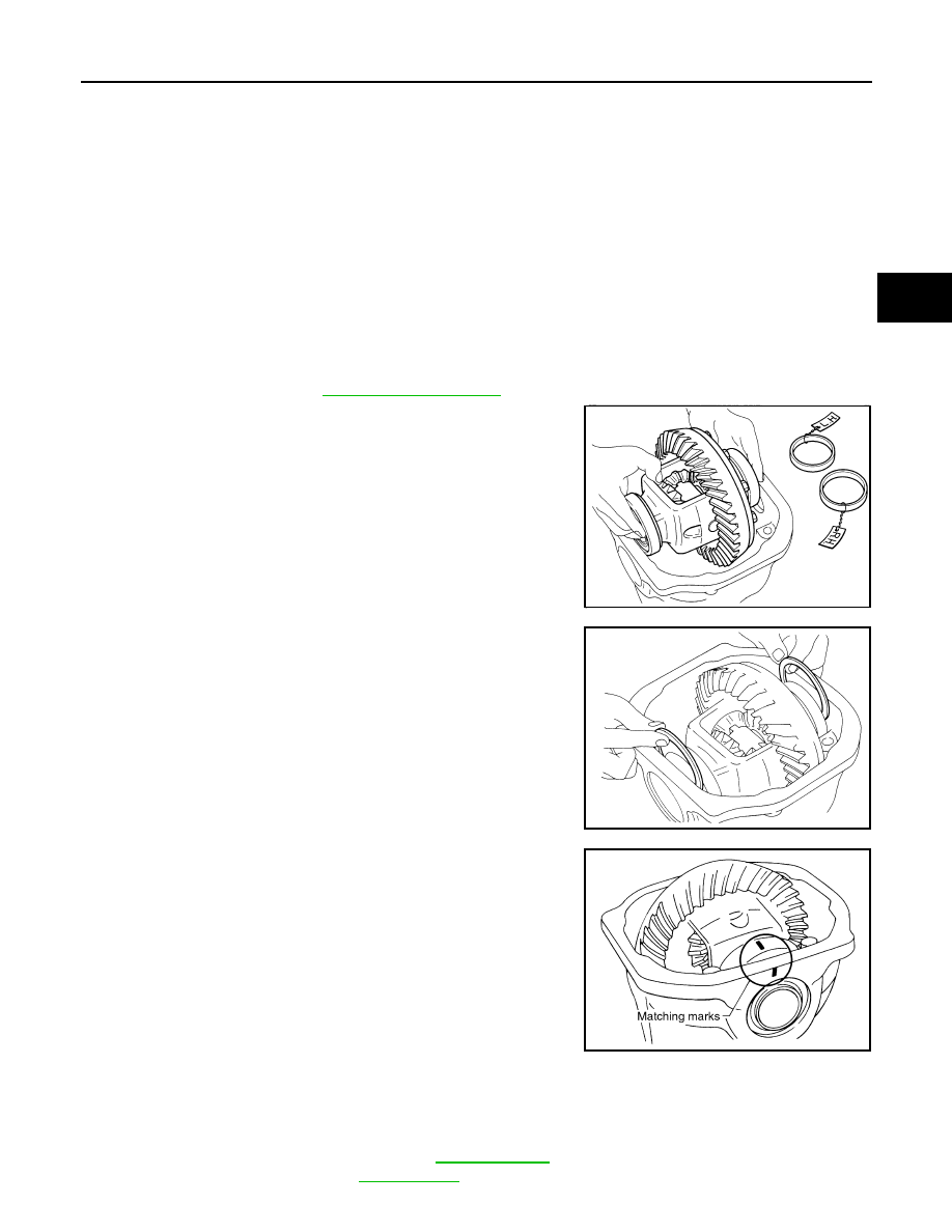
3.

Place the differential case, with side bearings and bearing races
installed, into gear carrier.

4.

Insert left and right original side bearing adjusting washers in
place between side bearings and gear carrier.

5.

Install bearing caps in their correct locations and tighten bearing
cap mounting bolts.

6.

Turn the carrier several times to seat the bearings.

7.

Measure the turning torque of the carrier at the drive gear mounting bolts with a spring gauge [SST: 

 (J-8129)].

When the preload torque is large

On pinion bearings:

Replace the collapsible spacer.

On side bearings:

Use thinner side bearing adjusting washers by the same amount to 
each side.

When the preload is small

On pinion bearings:

Tighten the drive pinion lock nut.

On side bearings:

Use thicker side bearing adjusting washers by the same amount to 
each side.

SPD527

SPD558

SDIA1795E

Standard

Specification

: Refer to 

DLN-294, "Pre-

load Torque"

.

DLN-284

< UNIT DISASSEMBLY AND ASSEMBLY >

[REAR FINAL DRIVE: R230]

DIFFERENTIAL ASSEMBLY

8.

If the turning torque is outside the specification, use a thicker/
thinner side bearing adjusting washer to adjust.

CAUTION:

Select a side bearing adjusting washer for right and left
individually.

9.

Record the total amount of washer thickness required for the correct carrier side bearing preload.

DRIVE GEAR RUNOUT

1.

Remove rear cover. Refer to 

DLN-276, "Disassembly"

.

2.

Fit a dial indicator to the drive gear back face.

3.

Rotate the drive gear to measure runout.

• If the runout is outside of the repair limit, check drive gear

assembly condition; foreign material may be caught between
drive gear and differential case, or differential case or drive
gear may be deformed, etc.

CAUTION:

Replace drive gear and drive pinion gear as a set.

TOOTH CONTACT

Before inspection and adjustment, drain gear oil.
1.

Remove rear cover. Refer to 

DLN-276, "Disassembly"

.

2.

Apply red lead to drive gear.

CAUTION:

Apply red lead to both the faces of 3 to 4 gears at 4 loca-
tions evenly spaced on drive gear.

3.

Rotate drive gear back and forth several times, check drive pin-
ion gear to drive gear tooth contact.

CAUTION:

Check tooth contact on drive side and reverse side.

If the turning torque is less 
than the specified range:

Use a thicker thrust wash-
er.

If the turning torque is 
greater than the specifica-
tion:

Use a thinner thrust wash-
er.

SPD772

Limit

Drive gear runout

: Refer to 

DLN-294, "Drive 

Gear Runout"

.

SPD886

SPD357

SDIA0570E

DIFFERENTIAL ASSEMBLY

DLN-285

< UNIT DISASSEMBLY AND ASSEMBLY >

[REAR FINAL DRIVE: R230]

C

E

F

G

H

I

J

K

L

M

A

B

DLN

N

O

P

4.

If tooth contact is improperly adjusted, follow the procedure
below to adjust the pinion height [dimension (X)].

• If the tooth contact is near the face (face contact), or near the

heel (heel contact), thicken pinion height adjusting washers to
move drive pinion closer to drive gear.

SDIA0207E

SDIA0517E

PDIA0440E

DLN-286

< UNIT DISASSEMBLY AND ASSEMBLY >

[REAR FINAL DRIVE: R230]

DIFFERENTIAL ASSEMBLY

• If the tooth contact is near the flank (flank contact), or near the

toe (toe contact), thin pinion height adjusting washers to move
drive pinion farther from drive gear.

BACKLASH

Before inspection and adjustment, drain gear oil.

1.

Remove rear cover. Refer to 

DLN-276, "Disassembly"

.

2.

Fit a dial indicator to the drive gear face to measure the back-
lash.

• If the backlash is outside of the specified value, change the

thickness of side bearing adjusting washer.

CAUTION:

Never change the total amount of washers as it changes the bearing preload.

Inspection After Disassembly

INFOID:0000000005249282

DRIVE GEAR AND DRIVE PINION

• Clean up the disassembled parts.
• If the gear teeth never mesh or line-up correctly, determine the cause and adjust or replace as necessary.
• If the gears are worn, cracked, damaged, pitted or chipped (by friction) noticeably, replace with new drive

gear and drive pinion as a set.

BEARING

• Clean up the disassembled parts.
• If any chipped (by friction), pitted, worn, rusted or scratched marks, or unusual noise from the bearing is

observed, replace as a bearing assembly (as a new set).

SIDE GEAR AND PINION MATE GEAR

• Clean up the disassembled parts.
• If any cracks or damage on the surface of the tooth is found, replace.
• If any worn or chipped mark on the contact sides of the thrust washer is found, replace.

SIDE GEAR THRUST WASHER AND PINION MATE THRUST WASHER

• Clean up the disassembled parts.
• If it is chipped (by friction), damaged, or unusually worn, replace.

OIL SEAL

• Whenever disassembled, replace.

PDIA0441E

Standard

Backlash

: Refer to 

DLN-294, "Back-

lash"

.

When the backlash is large:

Make drive gear back side adjusting washer thicker, 
and drive gear tooth side adjusting washer thinner by 
the same amount.

When the backlash is small:

Make drive gear back side adjusting washer thinner, 
and drive gear tooth side adjusting washer thicker by 
the same amount.

SPD513


Content   ..  610  611  612  613   ..