Infiniti FX35, FX50 (S51). Manual - part 578


  Index      Infiniti     Infiniti FX35, FX50 (S51) - service repair manual 2010 year


Search            


Content   ..  576  577  578  579   ..


Infiniti FX35, FX50 (S51). Manual - part 578


SIDE OIL SEAL

DLN-147

< REMOVAL AND INSTALLATION >

[FRONT FINAL DRIVE: F160A]

C

E

F

G

H

I

J

K

L

M

A

B

DLN

N

O

P

REMOVAL AND INSTALLATION

SIDE OIL SEAL

RIGHT SIDE

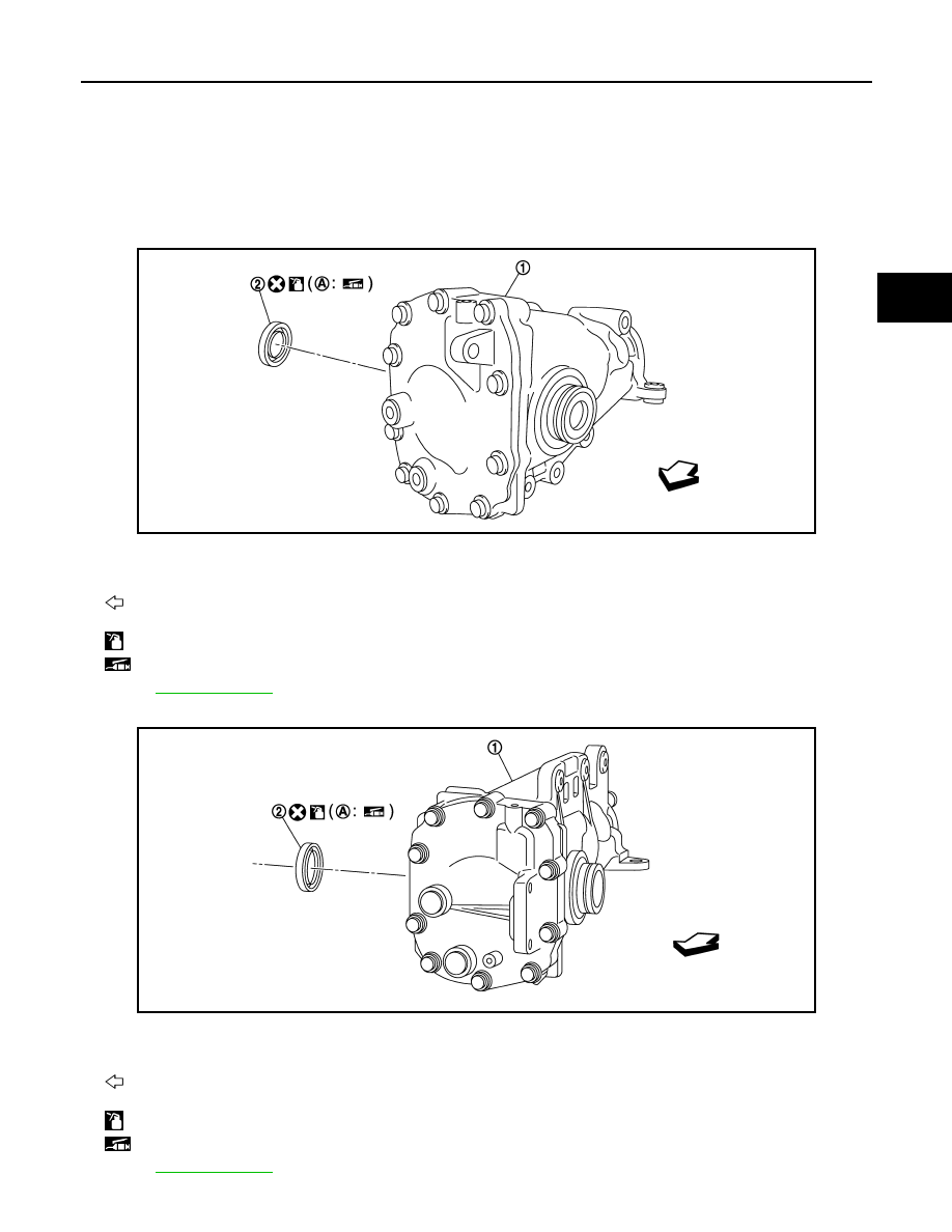
RIGHT SIDE : Exploded View

INFOID:0000000005249189

VQ35HR

VK50VE

JPDID0220ZZ

1.

Front final drive assembly

2.

Side oil seal (right side)

A:

Oil seal lip

: Vehicle front

: Apply gear oil.

: Apply multi-purpose grease.

Refer to 

GI-4, "Components"

 for symbols not described above.

JPDID0219ZZ

1.

Front final drive assembly

2.

Side oil seal (right side)

A:

Oil seal lip

: Vehicle front

: Apply gear oil.

: Apply multi-purpose grease.

Refer to 

GI-4, "Components"

 for symbols not described above.

DLN-148

< REMOVAL AND INSTALLATION >

[FRONT FINAL DRIVE: F160A]

SIDE OIL SEAL

RIGHT SIDE : Removal and Installation

INFOID:0000000005249190

REMOVAL

1.

Remove the front drive shaft. Refer to 

FAX-26, "Exploded View"

.

2.

Remove the side oil seal using a puller (A) [SST: KV381054S0
(J-34286)].

CAUTION:

Never damage gear carrier.

INSTALLATION

1.

Apply multi-purpose grease to sealing lips of side oil seal.

2.

Using the drift (A) [SST: ST33400001 (J-26082)], press-fit side
oil seal so that its surface comes face-to-face with the end sur-
face of the side retainer.

CAUTION:

• Never reuse oil seal.
• When installing, never incline oil seal.

3.

Install the front drive shaft. Refer to 

FAX-26, "Exploded View"

.

4.

When oil leaks while removing, check oil level after the installa-
tion. Refer to 

DLN-146, "Inspection"

.

LEFT SIDE

LEFT SIDE : Exploded View

INFOID:0000000005249191

VQ35HR

PDIA0838J

PDIA0787J

JSDIA0823ZZ

1.

Front final drive assembly

2.

Side oil seal (left side)

A:

Oil seal lip

: Vehicle front

: Apply gear oil.

SIDE OIL SEAL

DLN-149

< REMOVAL AND INSTALLATION >

[FRONT FINAL DRIVE: F160A]

C

E

F

G

H

I

J

K

L

M

A

B

DLN

N

O

P

VK50VE

LEFT SIDE : Removal and Installation

INFOID:0000000005249192

REMOVAL

1.

Remove the front final drive assembly from vehicle with power tool. Refer to 

DLN-150, "VQ35HR :

Exploded View"

 (VQ35HR), 

DLN-151, "VK50VE : Exploded View"

 (VK50VE).

NOTE:
Left side oil seal is attached to engine assembly. Replace it after removing front final drive assem-
bly from vehicle.

2.

Remove the side oil seal using a flat-bladed screwdriver.

CAUTION:

Never damage gear carrier.

INSTALLATION

1.

Apply multi-purpose grease to sealing lips of side oil seal.

2.

Using the drift (A) [SST: KV38102100 (J-25803-01)], press-fit
side oil seal so that its surface comes face-to-face with the end
surface of the gear carrier.

CAUTION:

• Never reuse oil seal.
• When installing, never incline oil seal.

3.

Install the front final drive assembly on vehicle. Refer to 

DLN-

150, "VQ35HR : Exploded View"

 (VQ35HR), 

DLN-151,

"VK50VE : Exploded View"

 (VK50VE).

4.

Install the front drive shaft. Refer to 

FAX-26, "Exploded View"

.

5.

When oil leaks while removing, check oil level after the installa-
tion. Refer to 

DLN-146, "Inspection"

.

: Apply multi-purpose grease.

Refer to 

GI-4, "Components"

 for symbols not described above.

JSDIA0824ZZ

1.

Front final drive assembly

2.

Side oil seal (left side)

A:

Oil seal lip

: Vehicle front

: Apply gear oil.

: Apply multi-purpose grease.

Refer to 

GI-4, "Components"

 for symbols not described above.

PDIA0788J

DLN-150

< UNIT REMOVAL AND INSTALLATION >

[FRONT FINAL DRIVE: F160A]

FRONT FINAL DRIVE ASSEMBLY

UNIT REMOVAL AND INSTALLATION

FRONT FINAL DRIVE ASSEMBLY

VQ35HR

VQ35HR : Exploded View

INFOID:0000000005249193

VQ35HR : Removal and Installation

INFOID:0000000005249194

REMOVAL

1.

Remove engine assembly from the vehicle. Refer to 

EM-87, "AWD : Removal and Installation"

.

2.

Separate engine assembly and suspension member.

3.

Remove engine mounting bracket (RH) (lower). Refer to 

EM-87, "AWD : Exploded View"

.

4.

Remove air breather hose and tube.

5.

Remove side shaft. Refer to 

DLN-153, "Exploded View"

.

6.

Remove final drive assembly mounting bolts with power tool and separate front final drive assembly from
engine.

INSTALLATION

Note the following, install in the reverse order of removal.
• When installing the side shaft, apply multi-purpose grease to contact surface of side shaft and side shaft oil

seal.

1.

Breather tube

2.

Breather hose

3.

Front final drive assembly

4.

Bushing

5.

Side shaft

: Vehicle front

Refer to 

GI-4, "Components"

 for symbols in the figure.

JPDID0221GB


Content   ..  576  577  578  579   ..