Infiniti FX35, FX50 (S51). Manual - part 536
HOOD LOCK
DLK-267
< REMOVAL AND INSTALLATION >
C
D
E
F
G
H
I
J
L
M
A
B
DLK
N
O
P
HOOD LOCK
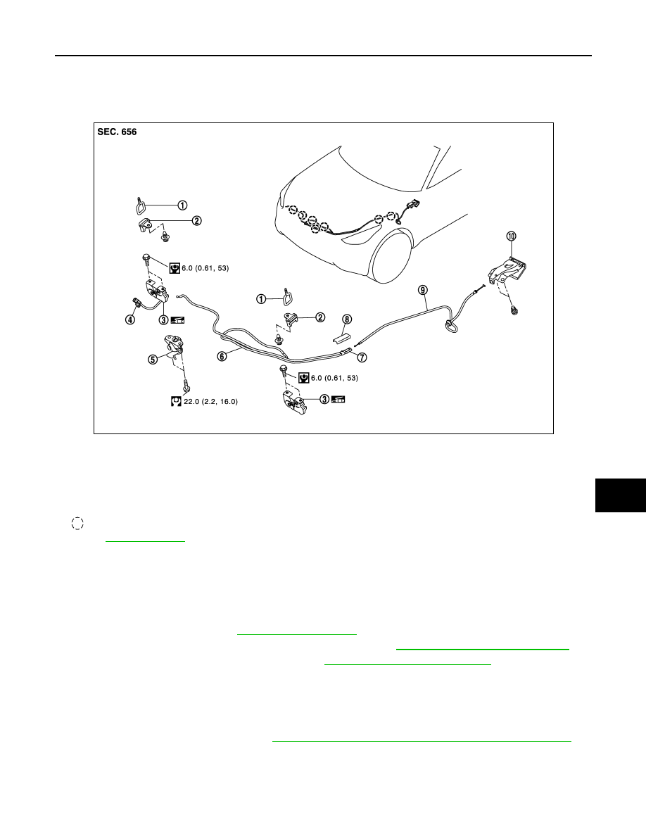
Exploded View
INFOID:0000000005239758
Removal and Installation
INFOID:0000000005239759
REMOVAL
CAUTION:
Before removal, confirm how the hood lock control cable is allocated and connected.
1.
Remove air duct (inlet). Refer to
2.
Remove engine room cover (LH/RH) (VK50VE models). Refer to
EM-175, "Removal and Installation"
.
3.
Remove air cleaner case assembly (RH). Refer to
EM-29, "Removal and Installation"
.
4.
Disconnect hood switch connector from head lamp bracket (RH).
5.
Remove mounting bolts and remove hood lock bracket (LH/RH).
6.
Disconnect hood lock control cable (front) from hood lock (LH/RH).
7.
Disassembly hood lock from hood lock bracket (LH/RH).
8.
Remove fender protector (LH). Refer to
EXT-25, "FENDER PROTECTOR : Removal and Installation"
9.
Remove clips of hood seal assembly (side) (LH) at the front side.
1.
Hood striker (LH/RH)
2.
Hood lock cover (LH/RH)
3.
Hood lock (LH/RH)
4.
Hood switch
5.
Secondary latch
6.
Hood lock control cable (front)
7.
Hood lock control cable protector
8.
Hood lock control cable protector
cover
9.
Hood lock control cable (rear)
10. Hood lock opener
: Clip
Refer to
JMKIA2644GB