Infiniti FX35, FX50 (S51). Manual - part 452
DEF-4
< SYSTEM DESCRIPTION >
REAR WINDOW DEFOGGER SYSTEM
SYSTEM DESCRIPTION
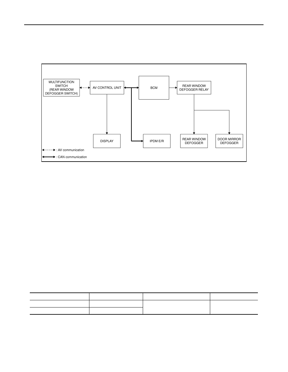
REAR WINDOW DEFOGGER SYSTEM
System Diagram
INFOID:0000000005249353
System Description
INFOID:0000000005249354
Operation Description
• Turn rear window defogger switch ON when the ignition switch turns ON. Then multifunction switch (rear
window defogger switch) transmits rear window defogger switch signal to AV control unit via AV communica-
tion. AV control unit transmits rear window defogger switch signal to BCM via CAN communication.
• BCM turns rear window defogger relay ON and transmits rear window defogger control signal to IPDM E/R
via CAN communication when rear window defogger switch signal is received.
• Rear window defogger and door mirror defogger (with mirror defogger) are supplied with power and operate
when rear window defogger relay turns ON.
• IPDM E/R transmits rear window defogger control signal to AV control unit via CAN communication.
• AV control unit transmit rear defogger indicator signal to multifunction switch (rear window defogger switch)
via AV communication, then rear window defogger indicator is illuminated.
Timer function
• BCM turns rear window defogger relay ON for approximately 15 minutes when rear window defogger switch
turns ON. It makes rear window defogger and door mirror defogger (with mirror defogger) operate.
• Timer is canceled after pressing rear window defogger switch again during timer operation. Then BCM turns
rear window defogger relay OFF. The same reaction also occurs during timer operation, if the ignition switch
is turned OFF.
INPUT/OUTPUT SIGNAL CHART
JMLIA0005GB
Switch
Input signal to BCM
BCM function
Actuator
Rear window defogger switch
Defogger switch signal
Rear window defogger and Door
mirror defogger control
Rear window defogger
Door mirror defogger
Push button ignition switch
Ignition signal