Infiniti FX35, FX50 (S51). Manual - part 240


  Index      Infiniti     Infiniti FX35, FX50 (S51) - service repair manual 2010 year


Search            


Content   ..  238  239  240  241   ..


Infiniti FX35, FX50 (S51). Manual - part 240


REAR DISC BRAKE

BR-57

< REMOVAL AND INSTALLATION >

C

D

E

G

H

I

J

K

L

M

A

B

BR

N

O

P

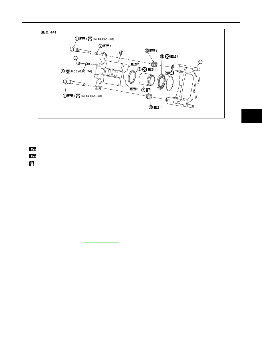
BRAKE CALIPER ASSEMBLY (1 PISTON TYPE) : Removal and Installation

INFOID:0000000005234216

REMOVAL

WARNING:

Clean any dust from the brake caliper and brake pads with a vacuum dust collector. Never blow with
compressed air.

CAUTION:

Never depress the brake pedal. Brake fluid may splash while removing the brake hose.

1.

Remove tires with power tool.

2.

Fix the disc rotor using wheel nuts.

3.

Drain brake fluid. Refer to 

BR-10, "Draining"

.

CAUTION:

Never spill or splash brake fluid on the disc rotor.

4.

Remove union bolt and copper washers, and disconnect brake hose from caliper assembly.

5.

Remove torque member mounting bolts, and remove brake caliper assembly.

CAUTION:

Never drop brake pad and caliper assembly.

6.

Remove disc rotor.

CAUTION:

• Put matching marks on the wheel hub and bearing assembly and the disc rotor before removing

the disc rotor.

• Never drop disc rotor.

INSTALLATION

WARNING:

Clean any dust from the brake caliper and brake pads with a vacuum dust collector. Never blow with
compressed air.

1.

Sliding pin bolt

2.

Bushing

3.

Cap

4.

Bleeder valve

5.

Cylinder body

6.

Piston seal

7.

Piston

8.

Piston boot

9.

Retaining ring

10.

Sliding pin boot

11. Torque member

 1: Apply rubber grease.

 2: Apply PBC (Poly Butyl Cuprysil) grease or silicone-based grease.

: Apply brake fluid.

Refer to 

GI-4, "Components"

 for symbols not described on the above.

JPFIA0388GB

BR-58

< REMOVAL AND INSTALLATION >

REAR DISC BRAKE

CAUTION:

Never depress the brake pedal. Brake fluid may splash while removing the brake hose.
1.

Install disc rotor.

CAUTION:

Align the matching marks that have been made during removal when reusing the disc rotor.

2.

Install the brake caliper assembly to the vehicle and tighten the torque member mounting bolts to the
specified torque.

CAUTION:

Never spill or splash any grease and moisture on the brake caliper assembly mounting face,
threads, mounting bolts, and washers. Wipe out any grease and moisture.

3.

Install brake hose and copper washers to brake caliper assembly, and tighten union bolts to the specified
torque. Refer to 

BR-24, "REAR : Exploded View"

.

4.

Refill with new brake fluid and perform the air bleeding. Refer to 

BR-11, "Bleeding Brake System"

.

CAUTION:

• Never reuse drained brake fluid.
• Never spill or splash brake fluid on the disc rotor.

5.

Check a drag of rear disc brake. If any drag is found, refer to 

BR-60, "BRAKE CALIPER ASSEMBLY (1

PISTON TYPE) : Inspection"

.

BRAKE CALIPER ASSEMBLY (1 PISTON TYPE) : Disassembly and Assembly

INFOID:0000000005234217

DISASSEMBLY

NOTE:
Never remove torque member and pad retainers when disassembling and assembling the cylinder body.

1.

Remove sliding pin bolts and remove the cylinder body from the torque member.

2.

Remove brake pads, shims and shim cover. Refer to 

BR-52, "BRAKE PAD (1 PISTON TYPE) : Exploded

View"

.

3.

Remove sliding pin boots from torque member.

4.

Remove bushing from sliding pin bolt.

5.

Remove retaining ring (1) from cylinder body using suitable tool
as shown in the figure.

6.

Place a wooden block as shown in the figure, and blow air from
union bolt mounting hole to remove piston and piston boot.

CAUTION:

Never get fingers caught in the piston.

JPFIA0042ZZ

BRD0041D

REAR DISC BRAKE

BR-59

< REMOVAL AND INSTALLATION >

C

D

E

G

H

I

J

K

L

M

A

B

BR

N

O

P

7.

Remove piston seal from cylinder body using suitable tool.

CAUTION:

Be careful not to damage a cylinder inner wall.

8.

Remove bleeder valve and cap.

ASSEMBLY

1.

Install bleeder valve and cap.

2.

Apply rubber grease to piston seal (1), and install them to cylin-
der body.

CAUTION:

Never reuse piston seal.

3.

Apply rubber grease to piston boot (1). Cover the piston (2) end
with the piston boot, and then install cylinder side lip on the pis-
ton boot securely into the groove on cylinder body.

CAUTION:

Never reuse piston boot.

4.

Apply brake fluid to piston (1). Push piston into cylinder body by
hand and push piston boot (2) piston side lip into the piston
groove.

CAUTION:

Press the piston evenly and vary the pressing point to pre-
vent cylinder inner wall from being rubbed.

JPFIA0038ZZ

JPFIA0039ZZ

JPFIA0040ZZ

JPFIA0041ZZ

BR-60

< REMOVAL AND INSTALLATION >

REAR DISC BRAKE

5.

Secure piston boot with retaining ring (1).

CAUTION:

• Make sure that boot is securely engaged in the groove on

cylinder body.

• Never reuse retaining ring.

6.

Apply rubber grease to bushing, and install bushing to sliding pin
bolt.

7.

Apply rubber grease to sliding pin boots, and install sliding pin
boot to torque member.

8.

Apply rubber grease to sliding pin bolts, and install the cylinder
body to the torque member and tighten the sliding pin bolt to the
specified torque.

9.

Install radius rod. Refer to 

RSU-15, "Exploded View"

.

BRAKE CALIPER ASSEMBLY (1 PISTON TYPE) : Inspection

INFOID:0000000005234218

INSPECTION AFTER DISASSEMBLY

Cylinder Body

Check the inner wall of the cylinder for rust, wear, cracks or damage. Replace the cylinder if any abnormal
condition is detected.

CAUTION:

Always clean with new brake fluid. Never clean with mineral oil such as gasoline and light oil.

Torque Member

Check the torque member for rust, wear, cracks or damage. Replace the member if any abnormal condition is
detected.

Piston

Check the piston for rust, wear, cracks or damage. Replace the piston if any abnormal condition is detected.

CAUTION:

A piston sliding surface is plated. Never polish with sandpaper.

Sliding Pin Bolt and Sliding Pin Boot

Check the sliding pin bolts and sliding pin boots for rust, wear, cracks or damage. Replace the parts if any
abnormal condition is detected.

INSPECTION AFTER INSTALLATION

1.

Check a drag of rear disc brake. If any drag is found, follow the procedure described below.

2.

Remove brake pads.

3.

Press the pistons.

CAUTION:

• Never damage the piston boot.
• When replacing a pad with new one, check a brake fluid level in the reservoir tank because brake

fluid returns to master cylinder reservoir tank when pressing piston in.

NOTE:
Use a disc brake piston tool to easily press piston.

4.

Install brake pads.

5.

Depress the brake pedal several times.

6.

Check a drag of rear disc brake again. If any drag is found, disassemble the cylinder body.

7.

Burnish contact surface between disc rotor and brake pads after refinishing or replacing disc rotor, or if a
soft pedal occurs at very low mileage. Refer to 

BR-16, "DISC ROTOR : Inspection and Adjustment"

.

BRAKE CALIPER ASSEMBLY (2 PISTON TYPE)

BRAKE CALIPER ASSEMBLY (2 PISTON TYPE) : Exploded View

INFOID:0000000005234219

REMOVAL

JPFIA0042ZZ


Content   ..  238  239  240  241   ..