Infiniti FX35, FX50 (S51). Manual - part 200
AV
BOSE AMP.
AV-573
< REMOVAL AND INSTALLATION >
[NAVIGATION (TWIN MONITOR)]
C
D
E
F
G
H
I
J
K
L
M
B
A
O
P
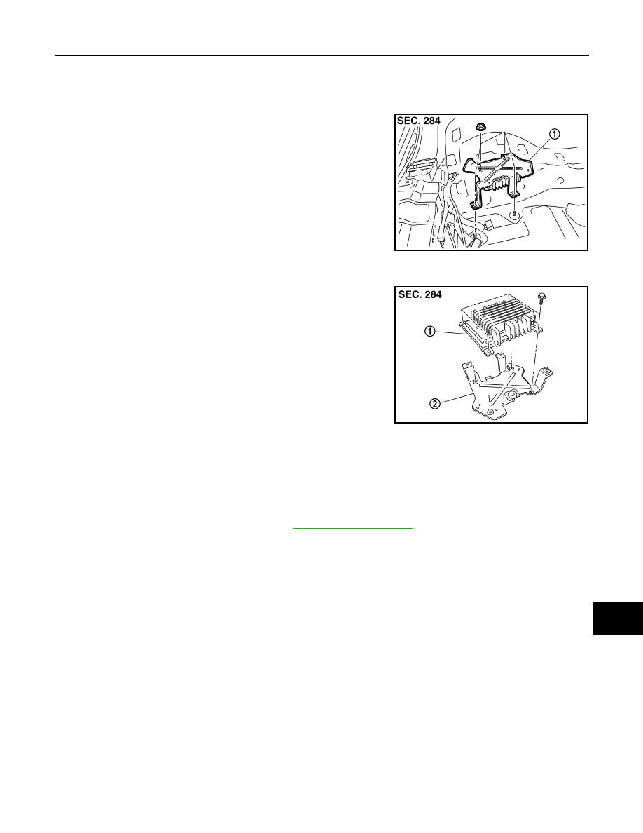
BOSE AMP.
Exploded View
INFOID:0000000005247420
REMOVAL
DISASSEMBLY
Removal and Installation
INFOID:0000000005247421
REMOVAL
1.
Remove luggage floor spacer (LH). Refer to
.
2.
Remove BOSE amp. mounting nuts.
3.
Disconnect connector and remove BOSE amp.
INSTALLATION
Installation is the reverse order of removal.
JSNIA1462ZZ
1.
BOSE amp.
JSNIA1539ZZ
1.
BOSE amp.
2.
Bracket