Content .. 1929 1930 1931 1932 ..
Infiniti FX35, FX50 (S51). Manual - part 1931
C1728 RECEIVER ID
WT-27
< DTC/CIRCUIT DIAGNOSIS >
C
D
F
G
H
I
J
K
L
M
A
B
WT
N
O
P
Is the inspection result normal?
YES
>> INSPECTION END
NO
>> GO TO 2.
2.
CHECK TIRE PRESSURE RECEIVER POWER SUPPLY CIRCUIT
1.
Disconnect the tire pressure receiver harness connector.
2.
Check the voltage between the tire pressure receiver harness connector and ground.
Is the inspection result normal?
YES
>> GO TO 3.
NO
>> Repair or replace the malfunctioning harness or connector.
3.
CHECK TIRE PRESSURE RECEIVER GROUND CIRCUIT
1.
Disconnect the low tire pressure warning control unit harness connector.
2.
Check the continuity between the low tire pressure warning control unit harness connector and tire pres-
sure receiver harness connector.
Is the inspection result normal?
YES
>> GO TO 4.
NO
>> Repair or replace the malfunctioning harness or connector.
4.
CHECK LOW TIRE PRESSURE WARNING CONTROL UNIT CIRCUIT
Check the low tire pressure warning control unit circuit. Refer to
.
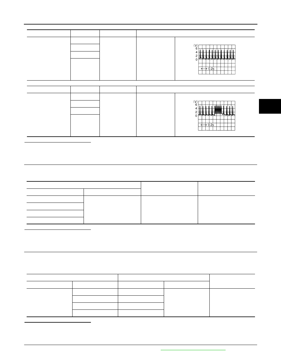
Connector
Terminal
—
Standard
M96
3
Ground
Stand by status
(Approx. 4.5 V)
4
5
6
Connector
Terminal
—
Standard
M96
3
Ground
When signal is re-
ceived
(Approx. 4.5 V)
4
5
6
OCC3879D
OCC3880D
Tire pressure receiver
—
Voltage
Connector
Terminal
E53 (Front LH)
1
Ground
7 - 16 V
E19 (Front RH)
B43 (Rear LH)
B251 (Rear RH)
Low tire pressure warning control unit
Tire pressure receiver
Continuity
Connector
Terminal
Connector
Terminal
M96
26
E53 (Front LH)
4
Existed
25
E19 (Front RH)
24
B43 (Rear LH)
23
B251 (Rear RH)