Content .. 1849 1850 1851 1852 ..
Infiniti FX35, FX50 (S51). Manual - part 1851
LOCK-UP CONTROL
TM-211
< SYSTEM DESCRIPTION >
[7AT: RE7R01B (VK50VE)]
C
E
F
G
H
I
J
K
L
M
A
B
TM
N
O
P
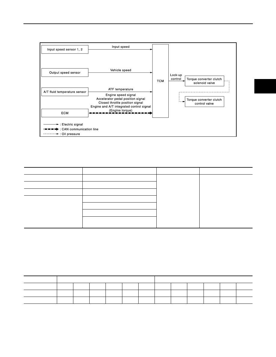
LOCK-UP CONTROL
System Diagram
INFOID:0000000005250207
System Description
INFOID:0000000005250208
INPUT/OUTPUT SIGNAL CHART
*: This signal is transmitted via CAN communication line.
SYSTEM DESCRIPTION
The torque converter clutch piston in the torque converter is engaged to eliminate torque converter slip to
increase power transmission efficiency.
The torque converter clutch control valve operation is controlled by the torque converter clutch solenoid valve,
which is controlled by a signal from TCM, and the torque converter clutch control valve engages or releases
the torque converter clutch piston.
Lock-up operation condition table
Torque Converter Clutch Control Valve Control
Lock-up control system diagram
JSDIA1350GB
Sensor
Input signal to TCM
TCM function
Actuator
Input speed sensor 1, 2
Input speed
Lock-up control
Torque converter clutch sole-
noid valve
↓
Torque converter clutch con-
trol valve
Output speed sensor
Vehicle speed
A/T fluid temperature sensor
ATF temperature
ECM
Engine speed signal*
Accelerator pedal position signal*
Closed throttle position signal*
Engine and A/T integrated control signal
(Engine torque)*
Selector lever
“D” position
“M” position
Gear position
7
6
5
4
3
2
7
6
5
4
3
2
Lock-up
×
–
–
–
–
–
×
×
×
×
×
×
Slip lock-up
×
×
×
×
×
×
×
×
×
×
×
×