Content .. 1841 1842 1843 1844 ..
Infiniti FX35, FX50 (S51). Manual - part 1843
FLUID COOLER SYSTEM
TM-179
< REMOVAL AND INSTALLATION >
[7AT: RE7R01A (VQ35HR)]
C
E
F
G
H
I
J
K
L
M
A
B
TM
N
O
P
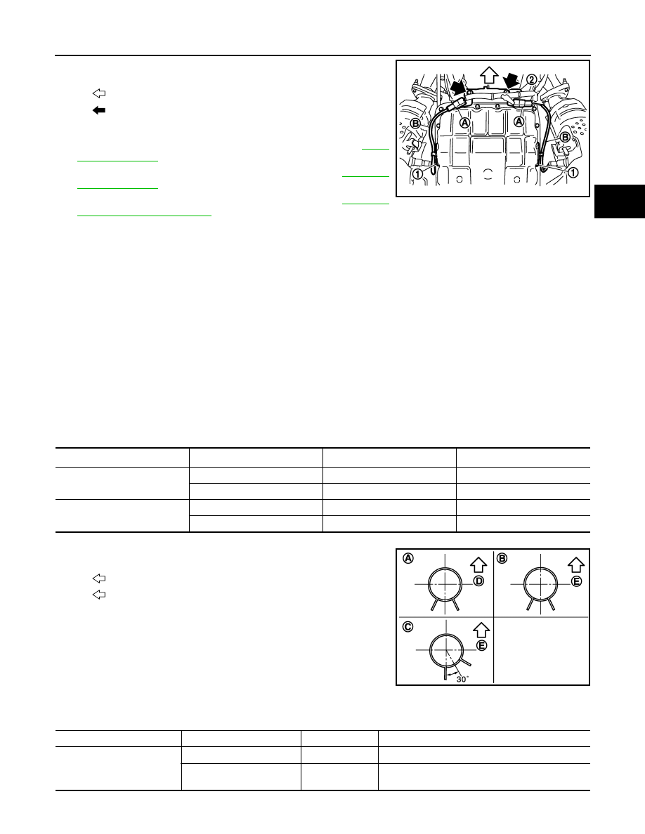
6.
Disconnect heated oxygen sensor 2 connectors (A).
7.
Remove heated oxygen sensor 2 harness (B) from clips (1).
8.
Remove harness bracket (2) from A/T assembly. Refer to
9.
Remove propeller shaft assembly (rear). Refer to
10. Remove propeller shaft assembly (front). Refer to
11. Lift up a transmission jack to make the gap between converter housing of A/T assembly and front suspen-
sion member.
CAUTION:
Never contact the A/T and transfer assembly with the lower lever of A/T shift selector when lifting
up a transmission jack.
12. Remove A/T fluid cooler tubes from A/T assembly and engine.
13. Plug up opening such as the A/T fluid cooler tube hole.
14. Remove clips and brackets.
15. Remove A/T fluid cooler tubes from the vehicle.
CAUTION:
Be careful not to bend A/T fluid cooler tubes.
INSTALLATION
Note the following, and install in the reverse order of removal.
CAUTION:
Never reuse copper washer.
• Refer to the following when installing A/T fluid cooler hoses.
*: Refer to the illustrations for the specific position each hose clamp tab.
- The illustrations indicate the view from the hose ends.
- When installing hose clamps center line of each hose clamp tab
should be positioned as shown in the figure.
- Insert A/T fluid cooler hoses according to dimension “L” described below.
: Vehicle front
: Bolt
SCIA8269E
Hose name
Hose end
Paint mark
Position of hose clamp
*
A/T fluid cooler hose A
Radiator assembly side
Facing backward
A
A/T fluid cooler tube side
Facing downward
B
A/T fluid cooler hose B
Radiator assembly side
Facing downward
C
A/T fluid cooler tube side
Facing downward
B
D
: Vehicle front
E
: Vehicle upper
JSDIA0795ZZ
(1)
(2)
Tube type
Dimension “L”
A/T fluid cooler hose A
Radiator assembly side
A
End reaches the radius curve end.
A/T fluid cooler tube side
B
30 mm (1.18 in) [End reaches the 2-stage bulge
(D).]