Infiniti FX35, FX50 (S51). Manual - part 1802


  Index      Infiniti     Infiniti FX35, FX50 (S51) - service repair manual 2010 year


Search            


Content   ..  1800  1801  1802  1803   ..


Infiniti FX35, FX50 (S51). Manual - part 1802


LINE PRESSURE CONTROL

TM-15

< SYSTEM DESCRIPTION >

[7AT: RE7R01A (VQ35HR)]

C

E

F

G

H

I

J

K

L

M

A

B

TM

N

O

P

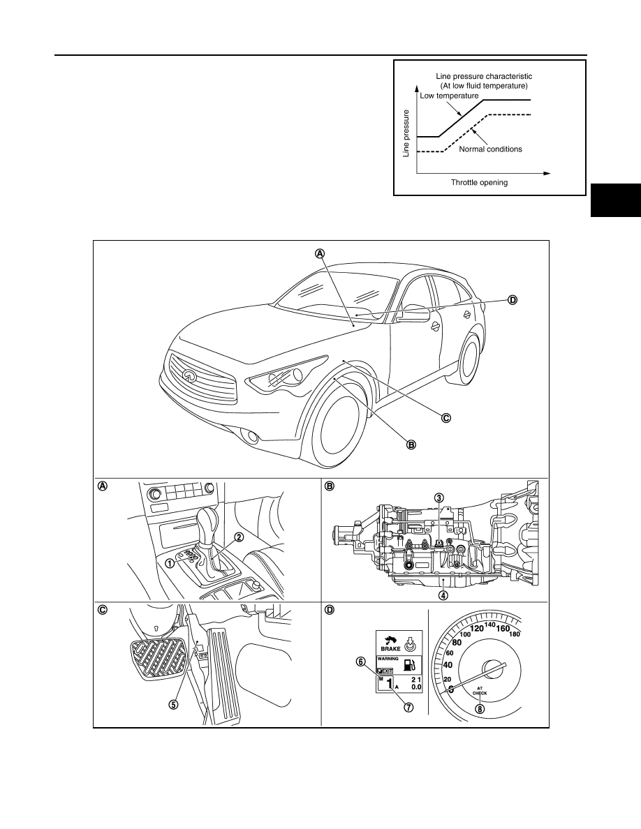
When the A/T fluid temperature drops below the prescribed tempera-
ture, in order to speed up the action of each friction element, the line
pressure is set higher than the normal line pressure characteristic.

Component Parts Location

INFOID:0000000005477008

PCIA0011E

1.

Selector lever position indicator

2.

A/T shift selector assembly

3.

A/T assembly connector

4.

Control valve with TCM*

5.

Accelerator pedal position sensor

6.

Manual mode indicator

7.

Shift position indicator

8.

A/T CHECK indicator lamp

JSDIA0782ZZ

TM-16

< SYSTEM DESCRIPTION >

[7AT: RE7R01A (VQ35HR)]

LINE PRESSURE CONTROL

NOTE:

• The following components are included in A/T shift selector assembly.

- Manual mode select switch

- Manual mode position select switch

- Shift position switch

• The following components are included in control valve with TCM.

- TCM

- Input speed sensor 1, 2

- Output speed sensor

- A/T fluid temperature sensor

- Transmission range switch

- Direct clutch solenoid valve

- High and low reverse clutch solenoid valve

- Input clutch solenoid valve

- Front brake solenoid valve

- Low brake solenoid valve

- Anti-interlock solenoid valve

- 2346 brake solenoid valve

- Line pressure solenoid valve

- Torque converter clutch solenoid valve

*: Control valve with TCM is included in A/T assembly.

Component Description

INFOID:0000000005249997

A.

Center console

B.

A/T assembly

C.

Accelerator pedal

D.

Combination meter

Name

Function

TCM

The TCM consists of a microcomputer and connectors for signal input and output and 
for power supply. The TCM controls the A/T.

Output speed sensor

TM-76, "Description"

Input speed sensor 1

TM-74, "Description"

Input speed sensor 2

A/T fluid temperature sensor

TM-72, "Description"

Line pressure solenoid valve

TM-97, "Description"

Pressure regulator valve

Adjusts the oil discharged from the oil pump to the optimum pressure (line pressure) for 
the driving state.

ECM

EC-30, "System Description"

SHIFT CHANGE CONTROL

TM-17

< SYSTEM DESCRIPTION >

[7AT: RE7R01A (VQ35HR)]

C

E

F

G

H

I

J

K

L

M

A

B

TM

N

O

P

SHIFT CHANGE CONTROL

System Diagram

INFOID:0000000005249998

System Description

INFOID:0000000005249999

INPUT/OUTPUT SIGNAL CHART

*: This signal is transmitted via CAN communication line.

SYSTEM DESCRIPTION

The clutch pressure control solenoid is controlled by the signals from the switches and sensors. Thus, the
clutch pressure is adjusted to be appropriate to the engine load state and vehicle driving state. It becomes

JSDIA1346GB

Sensor

Input signal to TCM

TCM function

Actuator

Input speed sensor 1, 2

Input speed

Shift change control

• High and low reverse 

clutch solenoid valve

• Direct clutch solenoid 

valve

• Input clutch solenoid valve
• Low brake solenoid valve
• 2346 brake solenoid valve
• Front brake solenoid valve
• Torque converter clutch so-

lenoid valve

• Line pressure solenoid 

valve

• Anti-interlock solenoid 

valve

Output speed sensor

Vehicle speed

A/T fluid temperature sensor

ATF temperature

ECM

Engine speed signal*

Accelerator pedal position signal*

Closed throttle position signal*

Engine and A/T integrated control signal
(Engine torque)*

BCM

Stop lamp switch signal*

TM-18

< SYSTEM DESCRIPTION >

[7AT: RE7R01A (VQ35HR)]

SHIFT CHANGE CONTROL

possible to finely control the clutch hydraulic pressure with high precision and a smoother shift change charac-
teristic is attained.

Shift Change

The clutch is controlled with the optimum timing and oil pressure by the engine speed, engine torque informa-
tion, etc.

Shift Change System Diagram

*1: Full phase real-time feedback control monitors movement of gear ratio at gear change, and controls oil
pressure in real-time to achieve the best gear ratio.

Blipping Control

This system makes transmission clutch engage readily by controlling (synchronizing) engine revolution
according to the (calculation of) engine revolution after shifting down.
• “BLIPPING CONTROL” functions.
- When downshifting by accelerator pedal depression.
- When downshifting by the manual mode.

PCIA0012E

PCIA0013E

JSDIA0826GB


Content   ..  1800  1801  1802  1803   ..