Infiniti FX35, FX50 (S51). Manual - part 1759


  Index      Infiniti     Infiniti FX35, FX50 (S51) - service repair manual 2010 year


Search            


Content   ..  1757  1758  1759  1760   ..


Infiniti FX35, FX50 (S51). Manual - part 1759


ST-28

< REMOVAL AND INSTALLATION >

STEERING GEAR AND LINKAGE

CAUTION:

Spiral cable may be cut if steering wheel turns while separating steering column assembly and steer-
ing gear assembly. Be sure to secure steering wheel using string to avoid turning.
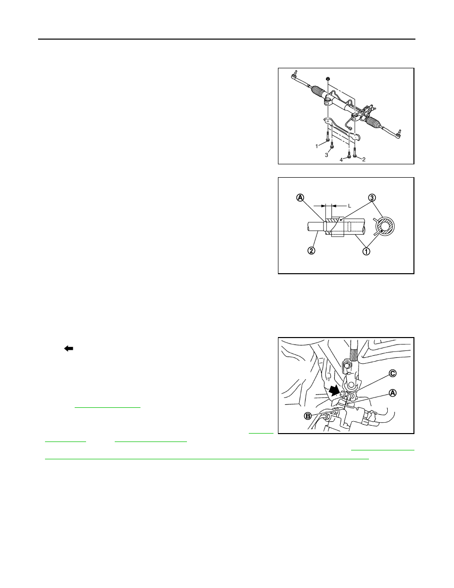
• Tighten the mounting bolts in the order shown in the figure when

installing the steering gear assembly.

CAUTION:

Never reuse the steering gear assembly mounting nut.

• When installing suction hoses (1), refer to the figure.

CAUTION:

• Never apply fluid to the hose (1) and tube (2).
• Insert hose securely until it contacts spool (A) of tube.
• Leave clearance (L) when installing clamp (3).

• When installing lower joint to steering gear assembly, follow the procedure listed below.
- Set rack of steering gear in the neutral position.

NOTE:
To get the neutral position of rack, turn gear-sub assembly and measure the distance of inner socket, and
then measure the intermediate position of the distance.

- Align rear cover cap projection (A) with the marking position of gear housing assembly (B).

- Install slit part of lower joint (C) aligning with the rear cover cap

projection (A). Make sure that the slit part of lower joint (C) is
aligned with rear cover cap projection (A) and the marking position
of gear housing assembly (B).

• After installation, bleed air from the steering hydraulic system.

Refer to 

ST-12, "Inspection"

.

• Perform final tightening of nuts and bolts on each part under

unladen conditions with tires on level ground when removing steer-
ing gear assembly. Check wheel alignment. Refer to 

FSU-8,

"Inspection"

 (2WD), 

FSU-26, "Inspection"

 (AWD).

• Adjust neutral position of steering angle sensor after checking wheel alignment. Refer to 

BRC-9, "ADJUST-

MENT OF STEERING ANGLE SENSOR NEUTRAL POSITION : Special Repair Requirement"

.

Disassembly and Assembly

INFOID:0000000005235284

DISASSEMBLY

1.

Remove low pressure piping.

CAUTION:

• Disassemble and assemble steering gear assembly by fixing the mounting area with a vise using

copper plates.

• Clean steering gear assembly with kerosene before disassembling. Be careful to avoid splash-

ing or applying any kerosene over connector of discharge port or return port.

2.

Remove cylinder tubes from gear housing assembly.

Temporary tightening: 1 

 2 

 3 

 4

Final tightening: 1 

 2 

 3 

 4

JSGIA0112ZZ

Standard

L

: 3 – 8 mm (0.12 – 0.31 in)

JSGIA0118ZZ

: Bolt

JSGIA0111ZZ

STEERING GEAR AND LINKAGE

ST-29

< REMOVAL AND INSTALLATION >

C

D

E

F

H

I

J

K

L

M

A

B

ST

N

O

P

3.

Remove rear cover cap from gear-sub assembly.

4.

Measure adjusting screw height “H”, and loosen adjusting
screw.

CAUTION:

• Never loosen adjusting screw 2 turns or more.
• Replace steering gear assembly if adjusting screw is

loosened 2 turns or more and it is removed.

5.

Remove gear-sub assembly from gear housing assembly.

6.

Remove O-ring from gear housing assembly.

7.

Loosen outer socket lock nut, and remove outer socket.

8.

Remove boot clamps, and then remove boot from inner socket.

CAUTION:

Never damage inner socket and gear housing assembly when removing boot. Inner socket and
gear housing assembly must be replaced if inner socket and gear housing assembly are damaged
because it may cause foreign material interfusion.

9.

Remove inner socket from gear housing assembly.

10. Drill out the clinching part of gear housing assembly (end cover

assembly side) outer rim with a 3 mm (0.12 in) drill bit. [Drill for
approximately 1.5 mm (0.059 in) depth.]

11. Remove end cover assembly with a 36 mm (1.42 in) open head

(commercial service tool).

CAUTION:

Never damage rack assembly surface when removing. Rack
assembly must be replaced if damaged because it may
cause fluid leakage.

12. Pull rack assembly together with rack oil seal (outer side) out

from gear housing assembly.

CAUTION:

Never damage cylinder inner wall when remove rack
assembly. Gear housing assembly must be replaced if dam-
aged because it may cause fluid leakage.

13. Heat rack Teflon ring to approximately 40

°

C (104

°

F) with a

dryer, and remove rack Teflon ring from rack assembly.

CAUTION:

Never damage rack assembly. Rack assembly must be
replaced if damaged because it may cause fluid leakage.

SGIA0624E

STC0013D

SST081B

SGIA0151E

ST-30

< REMOVAL AND INSTALLATION >

STEERING GEAR AND LINKAGE

14. Push rack oil seal inside with a 29 mm (1.14 in) socket and an

extension bar to push out rack oil seal (inner side) from gear
housing assembly.

CAUTION:

Never damage gear housing assembly and cylinder inner
wall. Gear housing assembly must be replaced if damaged
because it may cause fluid leakage.

ASSEMBLY

1.

Heat rack Teflon ring to approximately 40

°

C (104

°

F) with a dryer. Assemble it to mounting groove of rack

assembly.

CAUTION:

Never reuse rack Teflon ring.

2.

Install the Teflon ring correcting tool [SST: KV48104400 (

)] from tooth side of rack to fit rack Teflon ring on rack. Com-

press the ring with tool.

3.

Apply recommended grease to rack oil seal, and then install
rack oil seal in the following procedure. Then assemble rack
assembly to gear housing assembly.

CAUTION:

• Install rack oil seal in a direction so that the lip of inner oil

seal and the lip of outer oil seal face each other.

• Never damage retainer sliding surface by rack assembly.

Replace gear housing assembly if damaged.

• Never damage gear housing assembly inner wall by rack

assembly. Gear housing assembly must be replaced if
damaged because it may cause fluid leakage.

• Never reuse rack oil seal.

SGIA0179E

SGIA0153E

SGIA0154E

SGIA0205E

STEERING GEAR AND LINKAGE

ST-31

< REMOVAL AND INSTALLATION >

C

D

E

F

H

I

J

K

L

M

A

B

ST

N

O

P

a.

Wrap an OHP sheet [approximately 70 mm (2.76 in) 

×

 100 mm

(3.94 in)]. Around rack assembly teeth to avoid damaging rack
oil seal (inner). Install rack oil seal over sheet. Then, pull OHP
sheet along with rack oil seal until they pass rack assembly
teeth, and remove OHP sheet.

b.

Insert rack oil seal (inner) into rack assembly piston (rack Teflon
ring).

c.

Push retainer to adjusting screw side by hand, and move the
rack assembly inside the gear housing assembly so that the
rack oil seal (inner) can be pressed against the gear housing
assembly.

d.

Wrap an OHP sheet [approximately 70 mm (2.76 in) 

×

 100 mm

(3.94 in)]. Around the edge to avoid damaging rack oil seal
(outer). Install rack oil seal over sheet. Then, pull oil seal along
with OHP sheet until they pass rack edge, and remove OHP
sheet.

e.

Install end cover assembly to rack edge, and move rack oil seal
(outer) until it contacts with gear housing assembly.

4.

Tighten end cover assembly to specified torque using a 36 mm
(1.42 in) open head (commercial service tool).

CAUTION:

Never damage rack assembly. Replace it if damaged
because it may cause fluid leakage.

5.

Crimp gear housing assembly at one point using a punch as
shown in the figure so as to prevent end cover assembly from
getting loose after tightening end cover assembly.

6.

Apply recommended fluid to O-ring, and then install O-ring to
gear housing assembly.

7.

Install gear-sub assembly to gear housing assembly.

CAUTION:

In order to protect oil seal from any damage, insert gear-
sub assembly straightly.

8.

Install inner socket to gear housing assembly with the following
procedure.

SGIA0155E

PGIA0076E

SGIA0157E

SST081B

SGIA0871E


Content   ..  1757  1758  1759  1760   ..