Infiniti FX35, FX50 (S51). Manual - part 1585


  Index      Infiniti     Infiniti FX35, FX50 (S51) - service repair manual 2010 year


Search            


Content   ..  1583  1584  1585  1586   ..


Infiniti FX35, FX50 (S51). Manual - part 1585


REAR SEAT BELT

SB-15

< REMOVAL AND INSTALLATION >

C

D

E

F

G

I

J

K

L

M

A

B

SB

N

O

P

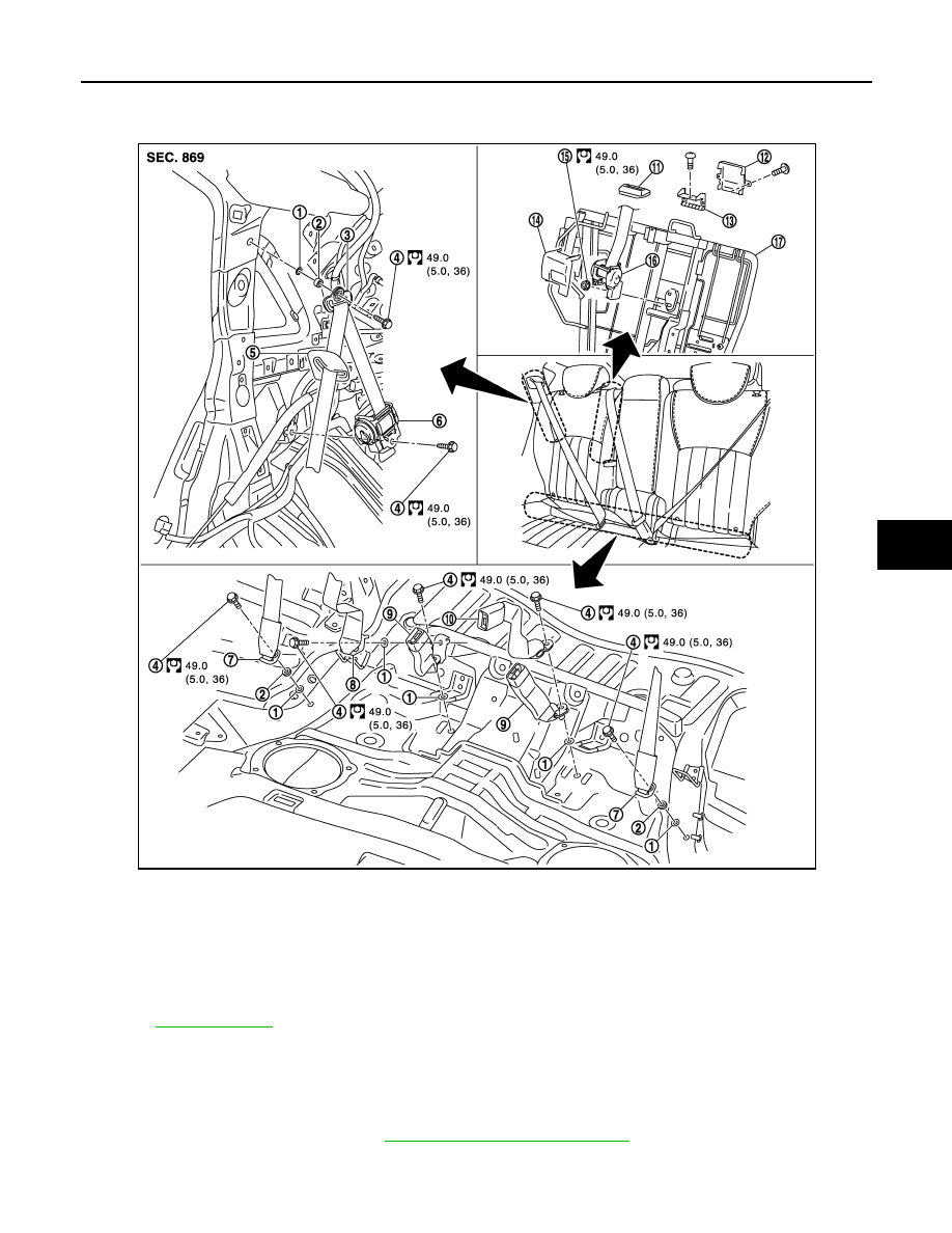
SEAT BELT BUCKLE : Exploded View

INFOID:0000000005243359

SEAT BELT BUCKLE : Removal and Installation

INFOID:0000000005243360

REMOVAL

Remove the center and outer seat belt buckle.
• Remove the rear seat cushion. Refer to 

SE-94, "Removal and Installation"

.

• Remove the center and outer seat belt buckle fixing anchor bolt.

1.

Retaining washer

2.

Spacer

3.

Shoulder anchor

4.

Anchor bolt

5.

Rear seat belt escutcheon

6.

Outer seat belt retractor

7.

Outer anchor

8.

Inner anchor 

9.

Outer seat belt buckle

10. Center seat belt buckle

11.

Seat belt finisher

12. Seat belt guide (upper)

13. Seat belt guide (lower)

14. Center seat belt retractor cover

15. Anchor nut

16. Center seat belt retractor

17. Seat back frame

Refer to 

GI-4, "Components"

 for symbols in the figure.

JMHIA0706GB

SB-16

< REMOVAL AND INSTALLATION >

REAR SEAT BELT

INSTALLATION

Install in the reverse order of removal.

LATCH SYSTEM FOR CHILDREN

SB-17

< REMOVAL AND INSTALLATION >

C

D

E

F

G

I

J

K

L

M

A

B

SB

N

O

P

LATCH SYSTEM FOR CHILDREN

Exploded View

INFOID:0000000005243361

Removal and Installation

INFOID:0000000005243362

REMOVAL

CAUTION:

Replace anchor bolts if they are deformed or worn out.

1.

Remove the rear seat cushion. Refer to 

SE-94, "Removal and Installation"

.

2.

Remove mounting bolts, and remove LATCH (Lower Anchor and Tether for Children) system. 

INSTALLATION

Install in the reverse order of removal.

1.

LATCH system

Refer to 

GI-4, "Components"

 for symbols in the figure.

JMHIA0707GB

SBC-1

RESTRAINTS

C

D

E

F

G

I

J

K

L

M

SECTION 

SBC

A

B

SBC

N

O

P

CONTENTS

SEAT BELT CONTROL SYSTEM

BASIC INSPECTION  ....................................

4

DIAGNOSIS AND REPAIR WORKFLOW  ..........

4

Work Flow  .................................................................

4

SYSTEM DESCRIPTION  ..............................

6

PRE-CRASH SEAT BELT SYSTEM  ...................

6

System Diagram ........................................................

6

System Description  ...................................................

6

Component Parts Location ........................................

8

Component Description .............................................

9

SEAT BELT WARNING SYSTEM ......................

10

System Diagram ......................................................

10

System Description  .................................................

10

Component Parts Location ......................................

11

Component Description ...........................................

11

DIAGNOSIS SYSTEM (PRE-CRASH SEAT 
BELT) .................................................................

12

CONSULT-III Function  ............................................

12

DTC/CIRCUIT DIAGNOSIS  .........................

14

U1000 CAN COMM CIRCUIT .............................

14

Description ..............................................................

14

DTC Logic  ...............................................................

14

B2451 SEAT BLT MTR DR CIRC  ......................

15

Description ..............................................................

15

DTC Logic  ...............................................................

15

Diagnosis Procedure ...............................................

15

B2452 SEAT BLT MTR AS CIRC  ......................

16

Description ..............................................................

16

DTC Logic  ...............................................................

16

Diagnosis Procedure ...............................................

16

B2453 BR STROKE SEN CIRC  .........................

17

Description ..............................................................

17

DTC Logic  ...............................................................

17

Diagnosis Procedure  ...............................................

17

Component Inspection .............................................

18

B2454 SEAT BLT PWR DR CIRC  ....................

20

Description ...............................................................

20

DTC Logic ................................................................

20

Diagnosis Procedure  ...............................................

20

B2455 CONTROL UNIT DR ..............................

22

Description ...............................................................

22

DTC Logic ................................................................

22

Diagnosis Procedure  ...............................................

22

B2456 SEAT BLT PWR AS  ..............................

23

Description ...............................................................

23

DTC Logic ................................................................

23

Diagnosis Procedure  ...............................................

23

B2457 CONTROL UNIT AS  ..............................

25

Description ...............................................................

25

DTC Logic ................................................................

25

Diagnosis Procedure  ...............................................

25

B2458 LOCAL COMM  ......................................

26

Description ...............................................................

26

DTC Logic ................................................................

26

Diagnosis Procedure  ...............................................

26

B2461 VHCL SPEED SIGNAL ..........................

28

Description ...............................................................

28

DTC Logic ................................................................

28

Diagnosis Procedure  ...............................................

28

B2462 VHCL DISTANCE SIGNAL  ...................

29

Description ...............................................................

29

DTC Logic ................................................................

29

Diagnosis Procedure  ...............................................

29

B2466 DR/AS CONTROL UNIT ........................

30

Description ...............................................................

30

DTC Logic ................................................................

30

Diagnosis Procedure  ...............................................

30


Content   ..  1583  1584  1585  1586   ..