Content .. 1517 1518 1519 1520 ..
Infiniti FX35, FX50 (S51). Manual - part 1519
FRONT POWER WINDOW SWITCH (PASSENGER SIDE)
PWC-137
< REMOVAL AND INSTALLATION >
[FRONT & REAR WINDOW ANTI-PINCH]
C
D
E
F
G
H
I
J
L
M
A
B
PWC
N
O
P
FRONT POWER WINDOW SWITCH (PASSENGER SIDE)
Removal and Installation
INFOID:0000000005248250
REMOVAL
1.
Remove the front door finisher.
Refer to
INT-11, "Removal and Installation"
.
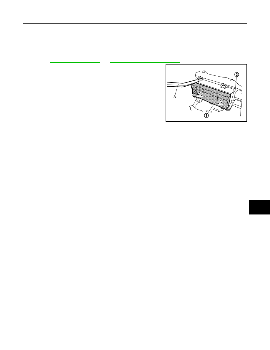
2.
Front power window switch (passenger side) (1) is removed
from front power window switch finisher (2) using flat-bladed
screw driver (A) etc.
CAUTION:
Never fold pawl of front door finisher.
INSTALLATION
Install in the reverse order of removal.
NOTE:
If front power window switch (passenger side) is replaced or is removed, it is necessary to perform the initial-
ization procedure.
JMKIA2756ZZ