Content .. 1425 1426 1427 1428 ..
Infiniti FX35, FX50 (S51). Manual - part 1427
PCS-66
< DTC/CIRCUIT DIAGNOSIS >
[POWER DISTRIBUTION SYSTEM]
PUSH-BUTTON IGNITION SWITCH
Component Inspection
INFOID:0000000005240700
1.
CHECK PUSH-BUTTON IGNITION SWITCH
1.
Turn ignition switch OFF.
2.
Disconnect push-button ignition switch connector.
3.
Check continuity between push-button ignition switch terminals.
Is the inspection result normal?
YES
>> INSPECTION END
NO
>> Replace push-button ignition switch. Refer to
PCS-133, "Removal and Installation"
.
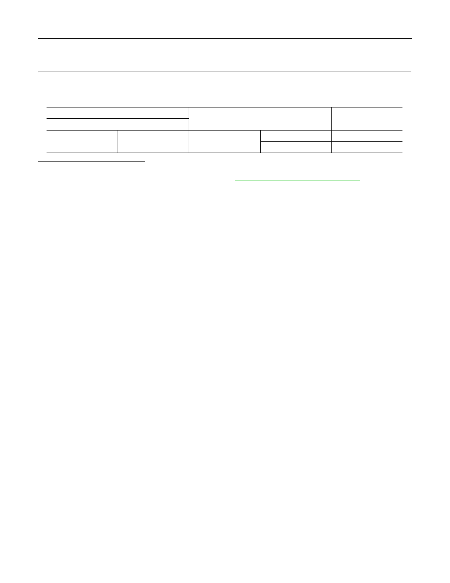
Push-button ignition switch
Condition
Continuity
Terminal
1
4
Push-button ignition
switch
Pressed
Existed
Not pressed
Not existed