Content .. 1356 1357 1358 1359 ..
Infiniti FX35, FX50 (S51). Manual - part 1358
OIL COOLER
LU-29
< REMOVAL AND INSTALLATION >
[VK50VE]
C
D
E
F
G
H
I
J
K
L
M
A
LU
N
P
O
REMOVAL AND INSTALLATION
OIL COOLER
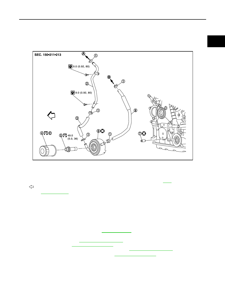
Exploded View
INFOID:0000000005245089
Removal and Installation
INFOID:0000000005245090
REMOVAL
WARNING:
Be careful not to get burned, as engine oil and engine coolant may be hot.
1.
Remove engine undercover with power tool.
2.
Drain engine coolant from radiator. Refer to
.
3.
Remove the following parts:
• Engine room cover: Refer to
• Reservoir tank: Refer to
.
• Alternator, water pump and A/C compressor belt: Refer to
.
4.
Remove water suction pipe mounting bolt. Refer to
5.
Disconnect water hoses and water pipe.
• When removing oil cooler only, pinch water hoses near oil cooler to prevent engine coolant from spilling
out.
• Remaining engine coolant in piping will come out. Use a tray to collect it.
CAUTION:
1.
Clamp
2.
Water pipe
3.
Water hose
4.
Oil filter
5.
Connector bolt
6.
Oil cooler
7.
Relief valve
8.
Water hose
A.
To water inlet
B.
To thermostat housing
C.
: Engine front
for symbols in the figure.
JPBIA2308GB