Infiniti FX35, FX50 (S51). Manual - part 1307


  Index      Infiniti     Infiniti FX35, FX50 (S51) - service repair manual 2010 year


Search            


Content   ..  1305  1306  1307  1308   ..


Infiniti FX35, FX50 (S51). Manual - part 1307


LAN-170

< DTC/CIRCUIT DIAGNOSIS >

[CAN SYSTEM (TYPE 3)]

CAN COMMUNICATION CIRCUIT 1

CAN COMMUNICATION CIRCUIT 1

Diagnosis Procedure

INFOID:0000000005576984

1.

CONNECTOR INSPECTION

1.

Turn the ignition switch OFF.

2.

Disconnect the battery cable from the negative terminal.

3.

Disconnect all the unit connectors on CAN communication circuit 1.

4.

Check terminals and connectors for damage, bend and loose connection.

Is the inspection result normal?

YES

>> GO TO 2.

NO

>> Repair the terminal and connector.

2.

CHECK HARNESS CONTINUITY (SHORT CIRCUIT)

Check the continuity between the data link connector terminals.

Is the inspection result normal?

YES

>> GO TO 3.

NO

>> Check the harness and repair the root cause.

3.

CHECK HARNESS CONTINUITY (SHORT CIRCUIT)

Check the continuity between the data link connector and the ground.

Is the inspection result normal?

YES

>> GO TO 4.

NO

>> Check the harness and repair the root cause.

4.

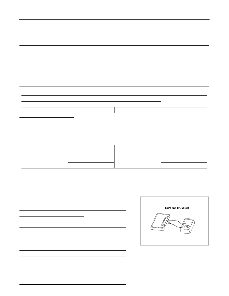
CHECK ECM AND IPDM E/R TERMINATION CIRCUIT

1.

Remove the ECM and the IPDM E/R.

2.

Check the resistance between the ECM terminals.

-

VQ engine models

-

VK engine models

3.

Check the resistance between the IPDM E/R terminals.

Data link connector

Continuity

Connector No.

Terminal No.

M24

6

14

Not existed

Data link connector

Ground

Continuity

Connector No.

Terminal No.

M24

6

Not existed

14

Not existed

ECM

Resistance (

)

Terminal No.

114

113

Approx. 108 – 132

ECM

Resistance (

)

Terminal No.

105

101

Approx. 108 – 132

IPDM E/R

Resistance (

)

Terminal No.

40

39

Approx. 108 – 132

LKIA0037E

LAN

CAN COMMUNICATION CIRCUIT 1

LAN-171

< DTC/CIRCUIT DIAGNOSIS >

[CAN SYSTEM (TYPE 3)]

C

D

E

F

G

H

I

J

K

L

B

A

O

P

N

Is the measurement value within the specification?

YES

>> GO TO 5.

NO

>> Replace the ECM and/or the IPDM E/R.

5.

CHECK SYMPTOM

Connect all the connectors. Check if the symptoms described in the “Symptom (Results from interview with
customer)” are reproduced. 

Inspection result

Reproduced>>GO TO 6.
Non-reproduced>>Start the diagnosis again. Follow the trouble diagnosis procedure when past error is

detected.

6.

CHECK UNIT REPRODUCTION

Perform the reproduction test as per the following procedure for each unit.
1.

Turn the ignition switch OFF.

2.

Disconnect the battery cable from the negative terminal.

3.

Disconnect one of the unit connectors of CAN communication circuit 1.
NOTE:
ECM and IPDM E/R have a termination circuit. Check other units first.

4.

Connect the battery cable to the negative terminal. Check if the symptoms described in the “Symptom
(Results from interview with customer)” are reproduced. 
NOTE:
Although unit-related error symptoms occur, do not confuse them with other symptoms. 

Inspection result

Reproduced>>Connect the connector. Check other units as per the above procedure.
Non-reproduced>>Replace the unit whose connector was disconnected.

LAN-172

< DTC/CIRCUIT DIAGNOSIS >

[CAN SYSTEM (TYPE 3)]

CAN COMMUNICATION CIRCUIT 2

CAN COMMUNICATION CIRCUIT 2

Diagnosis Procedure

INFOID:0000000005576985

1.

CONNECTOR INSPECTION

1.

Turn the ignition switch OFF.

2.

Disconnect the battery cable from the negative terminal.

3.

Disconnect all the unit connectors on CAN communication circuit 2.

4.

Check terminals and connectors for damage, bend and loose connection.

Is the inspection result normal?

YES

>> GO TO 2.

NO

>> Repair the terminal and connector.

2.

CHECK HARNESS CONTINUITY (SHORT CIRCUIT)

Check the continuity between the data link connector terminals.

Is the inspection result normal?

YES

>> GO TO 3.

NO

>> Check the harness and repair the root cause.

3.

CHECK HARNESS CONTINUITY (SHORT CIRCUIT)

Check the continuity between the data link connector and the ground.

Is the inspection result normal?

YES

>> GO TO 4.

NO

>> Check the harness and repair the root cause.

4.

CHECK CAN GATEWAY TERMINATION CIRCUIT

1.

Remove the CAN gateway.

2.

Check the resistance between the CAN gateway terminals.

Is the measurement value within the specification?

YES

>> GO TO 5.

NO

>> Replace the CAN gateway.

5.

CHECK SYMPTOM

Connect all the connectors. Check if the symptoms described in the “Symptom (Results from interview with
customer)” are reproduced. 

Inspection result

Reproduced>>GO TO 6.

Data link connector

Continuity

Connector No.

Terminal No.

M24

13

12

Not existed

Data link connector

Ground

Continuity

Connector No.

Terminal No.

M24

13

Not existed

12

Not existed

1

: CAN gateway

CAN gateway

Resistance (

)

Terminal No.

4

10

Approx. 108 – 132

6

12

Approx. 108 – 132

JPMIA0933ZZ

LAN

CAN COMMUNICATION CIRCUIT 2

LAN-173

< DTC/CIRCUIT DIAGNOSIS >

[CAN SYSTEM (TYPE 3)]

C

D

E

F

G

H

I

J

K

L

B

A

O

P

N

Non-reproduced>>Start the diagnosis again. Follow the trouble diagnosis procedure when past error is

detected.

6.

CHECK UNIT REPRODUCTION

Perform the reproduction test as per the following procedure for each unit.
1.

Turn the ignition switch OFF.

2.

Disconnect the battery cable from the negative terminal.

3.

Disconnect one of the unit connectors of CAN communication circuit 2.
NOTE:
CAN gateway have a termination circuit. Check other units first.

4.

Connect the battery cable to the negative terminal. Check if the symptoms described in the “Symptom
(Results from interview with customer)” are reproduced. 
NOTE:
Although unit-related error symptoms occur, do not confuse them with other symptoms. 

Inspection result

Reproduced>>Connect the connector. Check other units as per the above procedure.
Non-reproduced>>Replace the unit whose connector was disconnected.


Content   ..  1305  1306  1307  1308   ..