Content .. 1277 1278 1279 1280 ..
Infiniti FX35, FX50 (S51). Manual - part 1279
LAN-58
< DTC/CIRCUIT DIAGNOSIS >
[CAN]
MALFUNCTION AREA CHART
MALFUNCTION AREA CHART
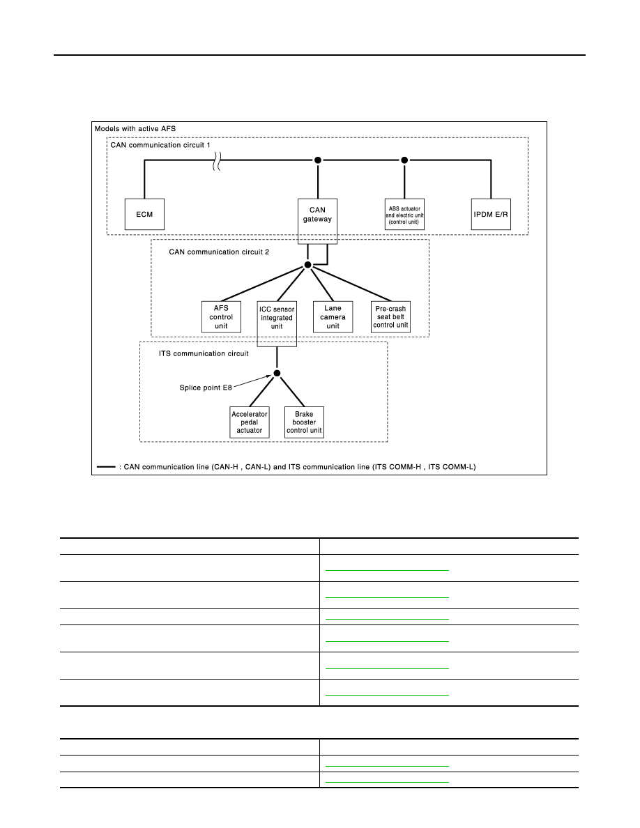
System Diagram
INFOID:0000000005241893
CAN Communication Circuit
INFOID:0000000005241894
MAIN LINE
BRANCH LINE
JSMIA0144GB
Malfunction area
Reference
Main line between data link connector and unified meter and A/C
amp.
Main line between unified meter and A/C amp. and driver seat
control unit
Main line between driver seat control unit and CAN gateway
Main line between CAN gateway and ABS actuator and electric
unit (control unit)
Main line between unified meter and A/C amp. and ABS actuator
and electric unit (control unit)
Main line between driver seat control unit and ABS actuator and
electric unit (control unit)
Malfunction area
Reference
ECM branch line circuit
AWD control unit branch line circuit