Content .. 1206 1207 1208 1209 ..
Infiniti FX35, FX50 (S51). Manual - part 1208
INL-32
< DTC/CIRCUIT DIAGNOSIS >
HOSPITALITY LIGHTING POWER SUPPLY CIRCUIT 1
Does continuity exist?
YES
>> GO TO 3.
NO
>> Repair the harnesses or connectors.
3.
CHECK ROOF MODULE CIRCUIT FOR OPEN
1.
Turn ignition switch OFF.
2.
Disconnect the following connectors.
-
Map lamp
-
Vanity mirror lamp (LH)
-
Vanity mirror lamp (RH)
-
Personal lamp
3.
Check continuity between the roof module harness connector and each lamp harness connectors.
Is the measurement value normal?
YES
>> Hospitality lighting power supply 1 circuit is normal.
NO
>> Repair the harnesses or connectors.
4.
CHECK HOSPITALITY LIGHTING POWER SUPPLY 1 CIRCUIT FOR SHORT
1.
Turn ignition switch OFF.
2.
Disconnect the following connectors.
-
Total illumination control unit
-
Roof module
-
Foot lamp (driver side)
-
Foot lamp (passenger side)
-
Mood lamp (rear door armrest LH)
-
Mood lamp (rear door armrest RH)
-
Push-button ignition switch
3.
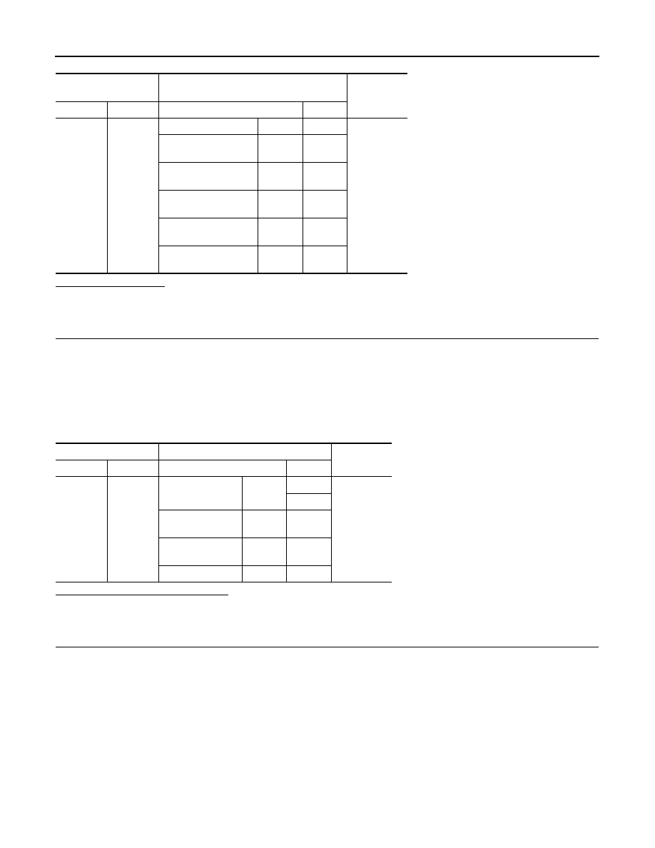
Check continuity between total illumination control unit harness connector and ground.
Total illumination con-
trol unit
Each interior room lamp
Continuity
Connector
Terminal
Connector
Terminal
M129
35
Roof module
R2
12
Existed
Foot lamp
(driver side)
M30
1
Foot lamp
(passenger side)
M130
1
Mood lamp
(rear door armrest LH)
D58
1
Mood lamp
(rear door armrest RH)
D78
1
Push-button ignition
switch
M50
3
Roof module
Each interior room lamp
Continuity
Connector
Terminal
Connector
Terminal
R11
12
Map lamp
R15
10
Existed
5
Vanity mirror lamp
(LH)
R12
2
Vanity mirror lamp
(RH)
R13
2
Personal lamp
R14
4