Content .. 1201 1202 1203 1204 ..
Infiniti FX35, FX50 (S51). Manual - part 1203
INL-12
< SYSTEM DESCRIPTION >
INTERIOR ROOM LAMP BATTERY SAVER SYSTEM
INTERIOR ROOM LAMP BATTERY SAVER SYSTEM
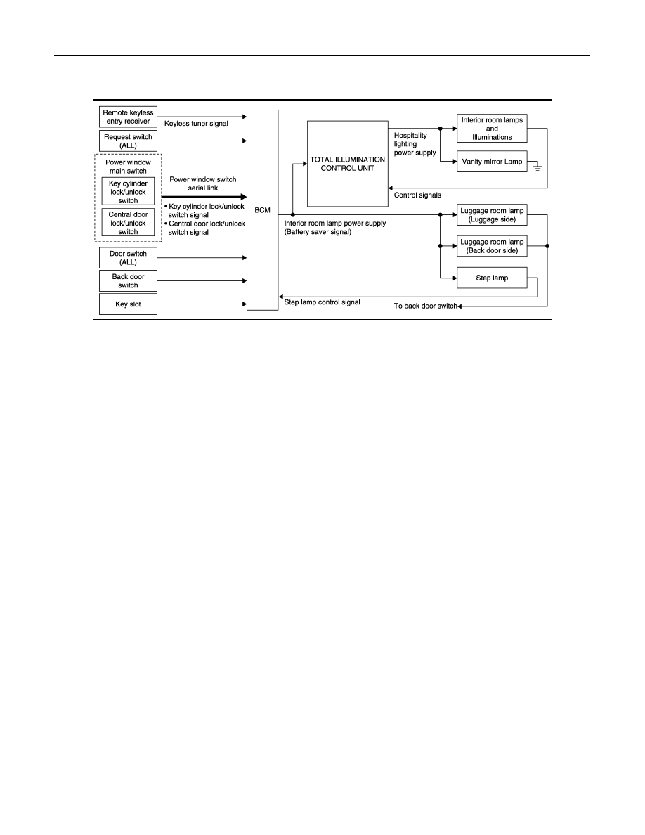
System Diagram
INFOID:0000000005245547
System Description
INFOID:0000000005245548
OUTLINE
• Interior room lamp battery saver is controlled by battery saver function of BCM.
• BCM cuts the interior room lamp power supply depending on the vehicle condition. Total illumination control
unit cuts the hospitality lighting power supply according to interior room lamp power supply (battery saver
signal). This function prevents the battery from over-discharging if the driver neglects turning OFF the lamps.
Applicable lamps
Control by the total illumination control unit
• Push-button ignition switch illumination
• Map lamp and personal lamps
• Center console indirect illumination
• Vanity mirror lamps
• Puddle lamps
• Foot lamps
• Mood lamps (Door armrest)
• Each illumination (Clock, switches, etc.)
Control by BCM
• Step lamps
• Luggage room lamps
INTERIOR ROOM LAMP BATTERY SAVER FUNCTION
• When the ignition switch is turned OFF, BCM operates the timer for a period of time to cut the interior room
lamp power supply.
• When interior room lamp power supply (battery saver signal) is OFF, the total illumination control unit cuts
hospitality lighting power supply. And then it switches to sleep mode.
• BCM restarts the timer when any of the following signals changes while operating the timer.
- Ignition switch status
- Door switch signal (ALL)
- Door lock/unlock signal (Remote keyless entry receiver, each request switch, key cylinder lock/unlock
switch, door lock/unlock switch)
- Back door switch signal
- Key switch signal (Key slot)
• BCM provides the interior room lamp power supply continuously when the ignition switch is in an other than
OFF.
NOTE:
JPLIA1207GB