Infiniti FX35, FX50 (S51). Manual - part 1181


  Index      Infiniti     Infiniti FX35, FX50 (S51) - service repair manual 2010 year


Search            


Content   ..  1179  1180  1181  1182   ..


Infiniti FX35, FX50 (S51). Manual - part 1181


ECM

HAC-121

< ECU DIAGNOSIS INFORMATION >

[AUTOMATIC AIR CONDITIONER]

C

D

E

F

G

H

J

K

L

M

A

B

HAC

N

O

P

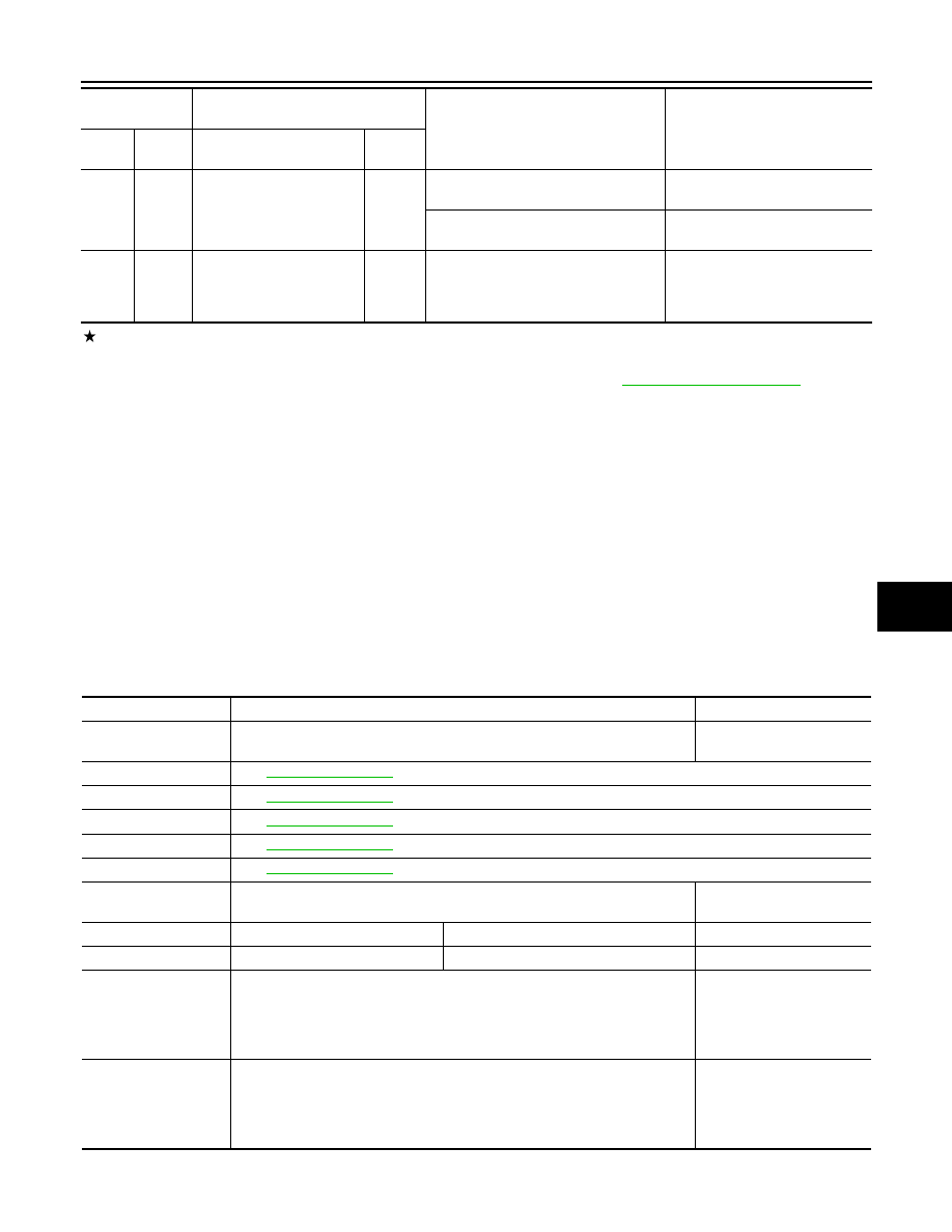
: Average voltage for pulse signal (Actual pulse signal can be confirmed by oscilloscope.)

*1: This may vary depending on internal resistance of the tester.

**2: Before measuring the terminal voltage, confirm that the battery is fully charged. Refer to 

PG-3, "How to Handle Battery"

.

*3: Models with ICC

*4: Models with ASCD

VK50VE

VK50VE : Reference Value

INFOID:0000000005597999

VALUES ON THE DIAGNOSIS TOOL

NOTE:
• Specification data are reference values.
• Specification data are output/input values which are detected or supplied by the ECM at the connector.

* Specification data may not be directly related to their components signals/values/operations.
i.e. Adjust ignition timing with a timing light before monitoring IGN TIMING, because the monitor may show
the specification data in spite of the ignition timing not being adjusted to the specification data. This IGN TIM-
ING monitors the data calculated by the ECM according to the signals input from the camshaft position sen-
sor and other ignition timing related sensors.

CONSULT-III MONITOR ITEM

126

(BR)

128

(B)

ICC brake switch (models 
with ICC system)
ASCD brake switch (mod-
els with ASCD system)

Input

[Ignition switch: ON]
• Brake pedal: Slightly depressed

0 V

[Ignition switch: ON]
• Brake pedal: Fully released

BATTERY VOLTAGE
(11 - 14 V)

127

(B)

128

(B)

ECM ground

Terminal No.

(Wire color)

Description

Condition

Value

(Approx.)

+

-–

Signal  name

Input/

Output

Monitor Item

Condition

Values/Status

ENG SPEED

• Run engine and compare CONSULT-III value with the tachometer indication.

Almost the same speed as 
the tachometer indication

MAS A/F SE-B1

See 

EC-728, "Description"

.

MAS A/F SE-B2

See 

EC-728, "Description"

.

B/FUEL SCHDL

See 

EC-728, "Description"

.

A/F ALPHA-B1

See 

EC-728, "Description"

.

A/F ALPHA-B2

See 

EC-728, "Description"

.

COOLAN TEMP/S

• Ignition switch: ON

Indicates engine coolant 
temperature

A/F SEN1 (B1)

• Engine: After warming up

Maintaining engine speed at 2,000 rpm

Fluctuates around 2.2 V

A/F SEN1 (B2)

• Engine: After warming up

Maintaining engine speed at 2,000 rpm

Fluctuates around 2.2 V

HO2S2 (B1)

• Revving engine from idle up to 3,000 rpm quickly after the following condi-

tions are met.

- Engine: After warming up
- After keeping engine speed between 3,500 and 4,000 rpm for 1 minute and 

at idle for 1 minute under no load

0 - 0.3 V 

←→

 Approx. 0.6 - 

1.0 V

HO2S2 (B2)

• Revving engine from idle up to 3,000 rpm quickly after the following condi-

tions are met.

- Engine: After warming up
- After keeping engine speed between 3,500 and 4,000 rpm for 1 minute and 

at idle for 1 minute under no load

0 - 0.3 V 

←→

 Approx. 0.6 - 

1.0 V

HAC-122

< ECU DIAGNOSIS INFORMATION >

[AUTOMATIC AIR CONDITIONER]

ECM

HO2S2 MNTR (B1)

• Revving engine from idle up to 3,000 rpm quickly after the following condi-

tions are met.

- Engine: After warming up
- After keeping engine speed between 3,500 and 4,000 rpm for 1 minute and 

at idle for 1 minute under no load

LEAN 

←→

 RICH

HO2S2 MNTR (B2)

• Revving engine from idle up to 3,000 rpm quickly after the following condi-

tions are met.

- Engine: After warming up
- After keeping engine speed between 3,500 and 4,000 rpm for 1 minute and 

at idle for 1 minute under no load

LEAN 

←→

 RICH

VHCL SPEED SE

• Turn drive wheels and compare CONSULT-III value with the speedometer in-

dication.

Almost the same speed as 
speedometer indication

BATTERY VOLT

• Ignition switch: ON (Engine stopped)

11 - 14 V

ACCEL SEN 1

• Ignition switch: ON

(Engine stopped)

Accelerator pedal: Fully released

0.45 - 1.0 V

Accelerator pedal: Fully depressed

4.4 - 4.8 V

ACCEL SEN 2*

1

• Ignition switch: ON

(Engine stopped)

Accelerator pedal: Fully released

0.45 - 1.0 V

Accelerator pedal: Fully depressed

4.3 - 4.8 V

TP SEN 1-B1

• Ignition switch: ON

(Engine stopped)

• Selector lever: D position

Accelerator pedal: Fully released

More than 0.36 V

Accelerator pedal: Fully depressed

Less than 4.75 V

TP SEN 2-B1*

1

• Ignition switch: ON

(Engine stopped)

• Selector lever: D position

Accelerator pedal: Fully released

More than 0.36 V

Accelerator pedal: Fully depressed

Less than 4.75 V

FUEL T/TMP SE

• Ignition switch: ON

Indicates fuel tank tempera-
ture

EVAP SYS PRES

• Ignition switch: ON

Approx. 1.8 - 4.8 V

FUEL LEVEL SE

• Ignition switch: ON

Depending on fuel level of 
fuel tank

START SIGNAL

• Ignition switch: ON 

 START 

 ON

OFF 

 ON 

 OFF

CLSD THL POS

• Ignition switch: ON

(Engine stopped)

Accelerator pedal: Fully released

ON

Accelerator pedal: Slightly depressed

OFF

AIR COND SIG

• Engine: After warming up, idle 

the engine

Air conditioner switch: OFF

OFF

Air conditioner switch: ON
(Compressor operates.)

ON

PW/ST SIGNAL

• Engine: After warming up, idle 

the engine

Steering wheel: Not being turned

OFF

Steering wheel: Being turned

ON

LOAD SIGNAL

• Ignition switch: ON

Rear window defogger switch: ON
and/or
Lighting switch: 2nd position

ON

Rear window defogger switch and lighting 
switch: OFF

OFF

IGNITION SW

• Ignition switch: ON 

 OFF 

 ON

ON 

 OFF 

 ON

HEATER FAN SW

• Engine: After warming up, idle 

the engine

Heater fan switch: ON

ON

Heater fan switch: OFF

OFF

BRAKE SW

• Ignition switch: ON

Brake pedal: Fully released

OFF

Brake pedal: Slightly depressed

ON

INJ PULSE-B1

• Engine: After warming up
• Selector lever: P or N position
• A/C switch: OFF
• No  load

Idle

2.0 - 3.0 msec

2,000 rpm

1.9 - 2.9 msec

Monitor Item

Condition

Values/Status

ECM

HAC-123

< ECU DIAGNOSIS INFORMATION >

[AUTOMATIC AIR CONDITIONER]

C

D

E

F

G

H

J

K

L

M

A

B

HAC

N

O

P

INJ PULSE-B2

• Engine: After warming up
• Selector lever: P or N position
• A/C switch: OFF
• No  load

Idle

2.0 - 3.0 msec

2,000 rpm

1.9 - 2.9 msec

IGN TIMING

• Engine: After warming up
• Selector lever: P or N position
• A/C switch: OFF
• No  load

Idle

12 - 22

°

BTDC

2,000 rpm

25 - 45

°

BTDC

CAL/LD VALUE

• Engine: After warming up
• Selector lever: P or N position
• A/C switch: OFF
• No  load

Idle

5 - 35%

2,500 rpm

5 - 35%

MASS AIRFLOW

• Engine: After warming up
• Selector lever: P or N position
• A/C switch: OFF
• No  load

Idle

2.0 - 6.0 g·m/s

2,500 rpm

7.0 - 20.0 g·m/s

PURG VOL C/V

• Engine: After warming up
• Selector lever: P or N position
• A/C switch: OFF
• No  load

Idle
(Accelerator pedal: Not depressed even 
slightly, after engine starting.)

0%

2,000 rpm

EXH/V TIM B1

• Engine: After warming up
• Selector lever: P or N position
• A/C switch: OFF
• No  load

Idle

5

°

 - 5

°

CA

Around 2,500 rpm while the engine speed 
is rising

Approx. 0 - 30

°

CA

EXH/V TIM B2

• Engine: After warming up
• Selector lever: P or N position
• A/C switch: OFF
• No  load

Idle

5 - 5

°

CA

Around 2,500 rpm while the engine speed 
is rising

Approx. 0 - 30

°

CA

INT/V SOL (B1)

• Engine: After warming up
• Selector lever: P or N position
• A/C switch: OFF
• No  load

Idle

0 - 2%

2,000 rpm

Approx. 0 - 50%

INT/V SOL (B2)

• Engine: After warming up
• Selector lever: P or N position
• A/C switch: OFF
• No  load

Idle

0 - 2%

2,000 rpm

Approx. 0 - 50%

AIR COND RLY

• Engine: After warming up, idle 

the engine

A/C switch: OFF

OFF

A/C switch: ON
(Compressor operates)

ON

VENT CONT/V

• Ignition switch: ON

OFF

THRTL RELAY

• Ignition switch: ON

ON

A/F S1 HTR (B1)

• Engine: After warming up, idle the engine

(More than 140 seconds after starting engine)

4 - 100%

A/F S1 HTR (B2)

• Engine: After warming up, idle the engine

(More than 140 seconds after starting engine)

4 - 100%

HO2S2 HTR (B1)

• Engine speed: Below 3,600 rpm after the following conditions are met.
- Engine: After warming up
- Keeping the engine speed between 3,500 and 4,000 rpm for 1 minute and at 

idle for 1 minute under no load

ON

• Engine speed: Above 3,600 rpm

OFF

HO2S2 HTR (B2)

• Engine speed: Below 3,600 rpm after the following conditions are met.
- Engine: After warming up
- Keeping the engine speed between 3,500 and 4,000 rpm for 1 minute and at 

idle for 1 minute under no load

ON

• Engine speed: Above 3,600 rpm

OFF

Monitor Item

Condition

Values/Status

HAC-124

< ECU DIAGNOSIS INFORMATION >

[AUTOMATIC AIR CONDITIONER]

ECM

ALT DUTY SIG

• Power generation voltage variable control: Operating

ON

• Power generation voltage variable control: Not operating

OFF

I/P PULLY SPD

• Vehicle speed: More than 20 km/h (12 MPH)

Almost the same speed as 
the tachometer indication

VEHICLE SPEED

• Turn drive wheels and compare CONSULT-III value with the speedometer in-

dication.

Almost the same speed as 
the speedometer indication

IDL A/V LEARN

• Engine: Running

Idle air volume learning has not been per-
formed yet.

YET

Idle air volume learning has already been 
performed successfully.

CMPLT

TRVL AFTER MIL

• Ignition switch: ON

Vehicle has traveled after MIL has illumi-
nated.

0 - 65,535 km
(0 - 40,723 miles)

SNOW MODE SW

• Ignition switch: ON

Snow mode switch: ON

ON

Snow mode switch: OFF

OFF

ENG OIL TEMP

• Engine: After warming up

More than 70

°

C (158

°

F)

VHCL SPEED SE

• Turn drive wheels and compare CONSULT-III value with the speedometer in-

dication.

Almost the same speed as 
the speedometer indication

SET VHCL SPD

• Engine: Running

ASCD: Operating

The preset vehicle speed is 
displayed

MAIN SW

• Ignition switch: ON

MAIN switch: Pressed

ON

MAIN switch: Released

OFF

CANCEL SW

• Ignition switch: ON

CANCEL switch: Pressed

ON

CANCEL switch: Released

OFF

RESUME/ACC SW

• Ignition switch: ON

RESUME/ACCELERATE switch: 
Pressed

ON

RESUME/ACCELERATE switch: Re-
leased

OFF

SET SW

• Ignition switch: ON

SET/COAST switch: Pressed

ON

SET/COAST switch: Released

OFF

BRAKE SW1
(ASCD/ICC brake 
switch)

• Ignition switch: ON

Brake pedal: Fully released

ON

Brake pedal: Slightly depressed

OFF

BRAKE SW2
(Stop lamp switch)

• Ignition switch: ON

Brake pedal: Fully released

OFF

Brake pedal: Slightly depressed

ON

DIST SW

• Ignition switch: ON

DISTANCE switch: Pressed

ON

DISTANCE switch: Released

OFF

VHCL SPD CUT

• Ignition switch: ON

NON

LO SPEED CUT

• Ignition switch: ON

NON

AT OD MONITOR

• Ignition switch: ON

OFF

AT OD CANCEL

• Ignition switch: ON

OFF

CRUISE LAMP

• Ignition switch: ON

MAIN switch: Pressed at the 1st time 


at the 2nd time

ON 

 OFF

SET LAMP

• MAIN switch: ON
• When vehicle speed is between 

40 km/h (25 MPH) and 144 km/
h (89 MPH)

ASCD: Operating

ON

ASCD: Not operating

OFF

EXH V/T LEARN

• Engine: Running

Exhaust Valve Timing Control Learning 
has not been performed yet.

YET

Exhaust Valve Timing Control Learning 
has not been performed yet.

CMPLT

Monitor Item

Condition

Values/Status


Content   ..  1179  1180  1181  1182   ..