Content .. 1178 1179 1180 1181 ..
Infiniti FX35, FX50 (S51). Manual - part 1180
ECM
HAC-117
< ECU DIAGNOSIS INFORMATION >
[AUTOMATIC AIR CONDITIONER]
C
D
E
F
G
H
J
K
L
M
A
B
HAC
N
O
P
77
(SB)
68
(LG)
Mass air flow sensor (bank
1)
Input
[Engine is running]
• Warm-up condition
• Idle speed
0.8 - 1.1 V
[Engine is running]
• Warm-up condition
• Engine speed: 2,500 rpm
1.4 - 1.7 V
78
(G)
84
(B)
Engine oil temperature
sensor
Input
[Engine is running]
0 - 4.8 V
Output voltage varies with engine
oil temperature.
79
(GR)
94
(LG)
Mass air flow sensor (bank
2)
Input
[Engine is running]
• Warm-up condition
• Idle speed
0.8 - 1.1 V
[Engine is running]
• Warm-up condition
• Engine speed: 2,500 rpm
1.4 - 1.7 V
80
(O)
84
(B)
Heated oxygen sensor 2
(bank 2)
Input
[Engine is running]
• Revving engine from idle to 3,000
rpm quickly after the following condi-
tions are met
- Engine: after warming up
- Keeping the engine speed between
3,500 and 4,000 rpm for 1 minute
and at idle for 1 minute under no load
0 - 1.0 V
81
(R)
128
(B)
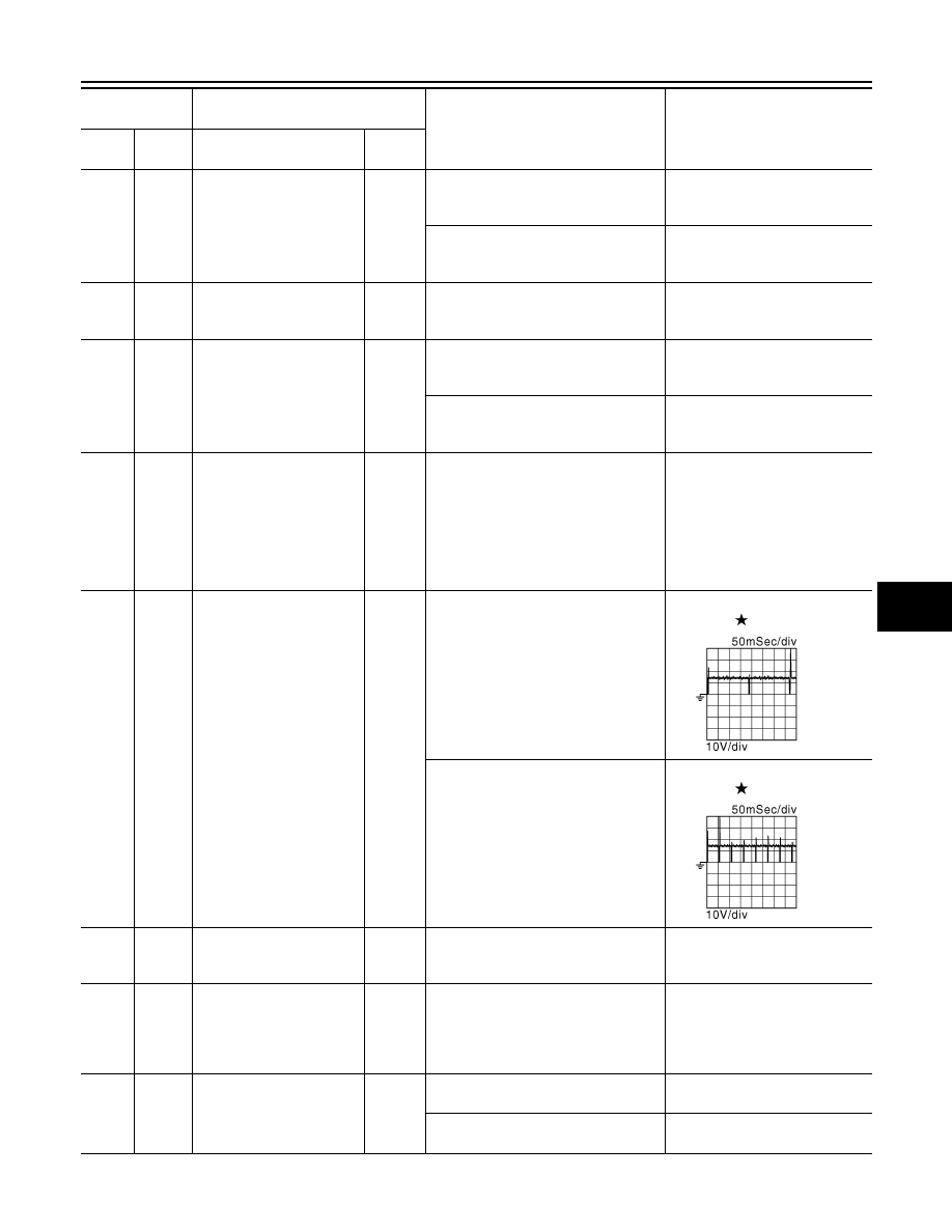
Fuel injector No. 3
Output
[Engine is running]
• Warm-up condition
• Idle speed
NOTE:
The pulse cycle changes depending
on rpm at idle
BATTERY VOLTAGE
(11 - 14 V)
82
(V)
Fuel injector No. 6
85
(BR)
Fuel injector No. 2
86
(W)
Fuel injector No. 5
[Engine is running]
• Warm-up condition
• Engine speed: 2,000 rpm
BATTERY VOLTAGE
(11 - 14 V)
89
(GR)
Fuel injector No. 1
90
(O)
Fuel injector No. 4
83
(R)
94
(LG)
Intake air temperature sen-
sor (bank 2)
Input
[Engine is running]
0 - 4.8 V
Output voltage varies with intake
air temperature.
84
(B)
—
Sensor ground
(Heated oxygen sensor 2,
Engine coolant tempera-
ture sensor, Engine oil tem-
perature sensor)
—
—
—
87
(Y)
96
(B)
Power steering pressure
sensor
Output
[Engine is running]
• Steering wheel: Being turned
0.5 - 4.5 V
[Engine is running]
• Steering wheel: Not being turned
0.4 - 0.8 V
Terminal No.
(Wire color)
Description
Condition
Value
(Approx.)
+
-–
Signal name
Input/
Output
JMBIA0047GB
JMBIA0048GB