Infiniti FX35, FX50 (S51). Manual - part 1175


  Index      Infiniti     Infiniti FX35, FX50 (S51) - service repair manual 2010 year


Search            


Content   ..  1173  1174  1175  1176   ..


Infiniti FX35, FX50 (S51). Manual - part 1175


INTAKE SENSOR

HAC-97

< DTC/CIRCUIT DIAGNOSIS >

[AUTOMATIC AIR CONDITIONER]

C

D

E

F

G

H

J

K

L

M

A

B

HAC

N

O

P

INTAKE SENSOR

Description

INFOID:0000000005246287
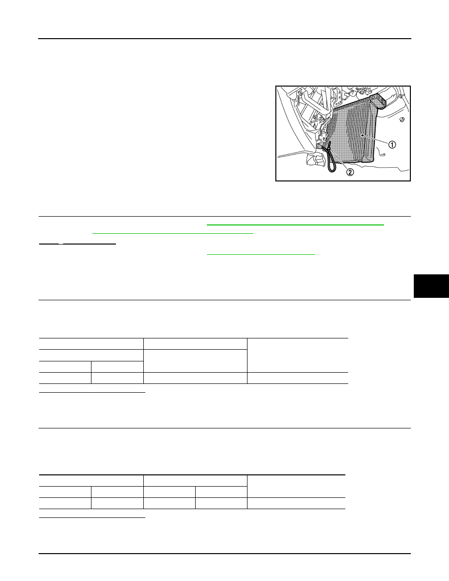
Intake Sensor
The intake sensor (2) is located on the evaporator. It converts air
temperature after it passes through the evaporator (1) into a resis-
tance value which is then input to the unified meter and A/C amp.

Component Function Check

INFOID:0000000005246288

1.

PERFORM SELF-DIAGNOSIS

Perform self-diagnosis function STEP-2. Refer to 

HAC-57, "WITHOUT ACCS : Diagnosis Description"

 (WITH-

OUT ACCS) or 

HAC-62, "WITH ACCS : Diagnosis Description"

 (WITH ACCS).

24 or 

24 is displayed.

YES

>> Go to Diagnosis Procedure. Refer to 

HAC-97, "Diagnosis Procedure"

.

NO

>> INSPECTION END

Diagnosis Procedure

INFOID:0000000005246289

1.

CHECK VOLTAGE BETWEEN INTAKE SENSOR AND GROUND

1.

Disconnect intake sensor connector.

2.

Turn ignition switch ON.

3.

Check voltage between intake sensor harness connector and ground.

Is the inspection result normal?

YES

>> GO TO 2.

NO

>> GO TO 4.

2.

CHECK CIRCUIT CONTINUITY BETWEEN INTAKE SENSOR AND UNIFIED METER AND A/C AMP.

1.

Turn ignition switch OFF.

2.

Disconnect unified meter and A/C amp. connector.

3.

Check continuity between intake sensor harness connector and unified meter and A/C amp. harness con-
nector.

Is the inspection result normal?

YES

>> GO TO 3.

NO

>> Repair harness or connector.

3.

CHECK INTAKE SENSOR

JPIIA0650ZZ

(+)

(

)

Voltage

Intake sensor

Connector

Terminal

M77

1

Ground

Approx. 5 V

Intake sensor

Unified meter and A/C amp.

Continuity

Connector

Terminal

Connector

Terminal

M77

2

M67

59

Existed

HAC-98

< DTC/CIRCUIT DIAGNOSIS >

[AUTOMATIC AIR CONDITIONER]

INTAKE SENSOR

Check intake sensor. Refer to 

HAC-98, "Component Inspection"

.

Is the inspection result normal?

YES

>> Replace unified meter and A/C amp.

NO

>> Replace intake sensor.

4.

CHECK CIRCUIT CONTINUITY BETWEEN INTAKE SENSOR AND UNIFIED METER AND A/C AMP.

1.

Turn ignition switch OFF.

2.

Disconnect unified meter and A/C amp. connector.

3.

Check continuity between intake sensor harness connector and unified meter and A/C amp. harness con-
nector.

4.

Check continuity between intake sensor harness connector and ground.

Is the inspection result normal?

YES

>> Replace unified meter and A/C amp.

NO

>> Repair harness or connector.

Component Inspection

INFOID:0000000005246290

1.

CHECK INTAKE SENSOR

1.

Turn ignition switch OFF.

2.

Disconnect intake sensor connector.

3.

Check resistance between intake sensor terminals.

Is the inspection result normal?

YES

>> INSPECTION END

NO

>> Replace intake sensor.

Intake sensor

Unified meter and A/C amp.

Continuity

Connector

Terminal

Connector

Terminal

M77

1

M67

43

Existed

Intake sensor

Continuity

Connector

Terminal

M77

1

Ground

Not existed

Terminal

Condition

Resistance k

Temperature 

°

C (

°

F)

1

2

15 (5)

12.34

10 (14)

9.62

5 (23)

7.56

0 (32)

6.00

5 (41)

4.80

10 (50)

3.87

15 (59)

3.15

20 (68)

2.57

25 (77)

2.12

30 (86)

1.76

35 (95)

1.47

40 (104)

1.23

45 (113)

1.04

GAS SENSOR

HAC-99

< DTC/CIRCUIT DIAGNOSIS >

[AUTOMATIC AIR CONDITIONER]

C

D

E

F

G

H

J

K

L

M

A

B

HAC

N

O

P

GAS SENSOR

Description

INFOID:0000000005246291

COMPONENT DESCRIPTION

Gas Sensor

The gas sensor (1) is attached on the radiator core support. It
detects smell of exhaust gas and converts it into a duty ratio which is
then input into the unified meter and A/C amp.

SMELL OF EXHAUST GAS INPUT PROCESS

Gas sensor detects ambient atmospheric CO and NO

2

, and converts them to values of resistance. The values

are converted to signals with the gas sensor internal circuit, then the unified meter and A/C amp. inputs the
signals.
Gas sensor has a construction that detects CO and NO

2

 by gas sensor element from the air intake of the case

through a filter (waterproof sheet). It sends output signals to the unified meter and A/C amp. in response to a
resistance value conversion by gas sensor elements. Output signals prevent a smell of exhaust gas from get-
ting into vehicle by performing corrections according to various driving conditions.

Component Function Check

INFOID:0000000005246292

1.

PERFORM SELF-DIAGNOSIS

Perform self-diagnosis function STEP-2. Refer to 

HAC-62, "WITH ACCS : Diagnosis Description"

.

28, 

28, 29 or 

29 is displayed.

YES

>> Go to Diagnosis Procedure. Refer to 

HAC-99, "Diagnosis Procedure"

.

NO

>> INSPECTION END

Diagnosis Procedure

INFOID:0000000005246293

1.

CHECK POWER SUPPLY FOR GAS SENSOR

1.

Turn ignition switch OFF.

2.

Disconnect gas sensor connector.

3.

Turn ignition switch ON.

4.

Check voltage between gas sensor harness connector and ground.

JSIIA1147ZZ

PJIA0049E

HAC-100

< DTC/CIRCUIT DIAGNOSIS >

[AUTOMATIC AIR CONDITIONER]

GAS SENSOR

Is the inspection result normal?

YES

>> GO TO 2.

NO

>>

Check power supply circuit and 10A fuse (No. 3, located in the fuse block). Refer to 

PG-156,

"Fuse, Connector and Terminal Arrangement"

• If fuse is OK, check harness for open circuit. Repair or replace if necessary.
• If fuse is NG, check harness for short circuit and replace fuse.

2.

CHECK GROUND CIRCUIT FOR GAS SENSOR 

1.

Turn ignition switch OFF.

2.

Check continuity between gas sensor harness connector and ground.

Is the inspection result normal?

YES

>> GO TO 3.

NO

>> Repair harness or connector.

3.

CHECK GAS SENSOR SIGNAL 

1.

Reconnect gas sensor connector.

2.

Turn ignition switch ON.

3.

Check signal between gas sensor harness connector and ground using an oscilloscope.

NOTE:
The signal is different by measurement environment of a vehicle.

Is the inspection result normal?

YES

>> GO TO 4.

NO

>> Replace gas sensor.

4.

CHECK CIRCUIT CONTINUITY BETWEEN UNIFIED METER AND A/C AMP. AND GAS SENSOR

1.

Turn ignition switch OFF.

2.

Disconnect unified meter and A/C amp. connector.

3.

Check continuity between unified meter and A/C amp. harness connector and gas sensor harness con-
nector.

(+)

(

)

Voltage

Gas sensor

Connector

Terminal

E75

1

Ground

Battery voltage

Gas sensor

Continuity

Connector

Terminal

E75

2

Ground

Existed

(+)

(

)

Voltage

Gas sensor

Connector

Terminal

E75

3

Ground

ZJIA1163J

Gas sensor

Unified meter and A/C amp.

Continuity

Connector

Terminal

Connector

Terminal

E75

3

M67

47

Existed


Content   ..  1173  1174  1175  1176   ..