Content .. 1133 1134 1135 1136 ..
Infiniti FX35, FX50 (S51). Manual - part 1135
HEATER & COOLING UNIT ASSEMBLY
HA-53
< REMOVAL AND INSTALLATION >
[VQ35HR]
C
D
E
F
G
H
J
K
L
M
A
B
HA
N
O
P
HEATER & COOLING UNIT ASSEMBLY
HEATER & COOLING UNIT ASSEMBLY : Removal and Installation
INFOID:0000000005249920
REMOVAL
1.
Set the temperature at 18.0
°
C (60
°
F).
2.
Disconnect the battery cable from the negative terminal.
3.
Use a refrigerant collecting equipment (for HFC-134a) to discharge the refrigerant.
4.
Drain engine coolant from cooling system. Refer to
5.
Remove cowl top cover. Refer to
6.
Remove engine cover. Refer to
.
7.
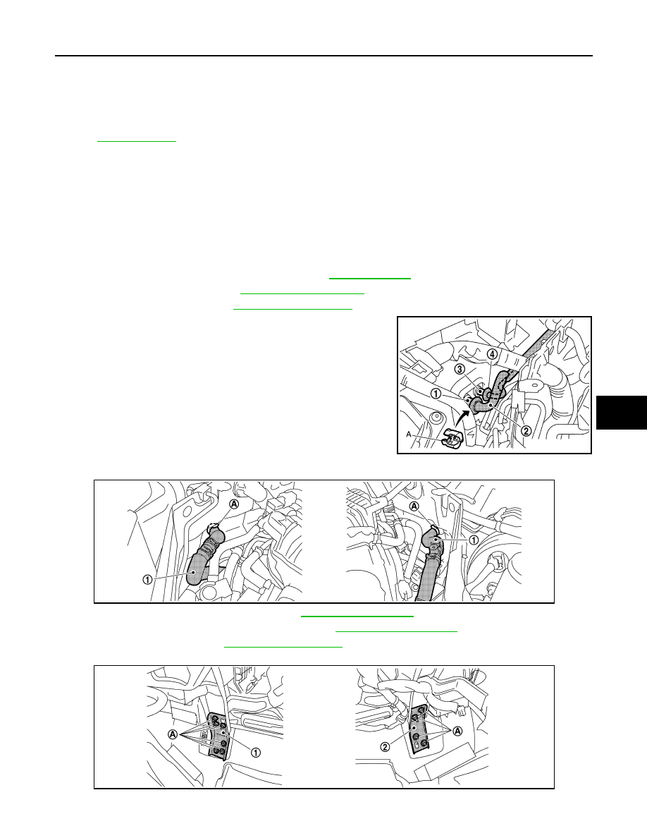
Disconnect one-touch joint between low-pressure pipe 1 (1) and
low-pressure pipe 2 (2) with disconnector (SST: 9253089916)
(A).
CAUTION:
Cap or wrap the joint of the A/C piping with suitable mate-
rial such as vinyl tape to avoid the entry of air.
8.
Disconnect one-touch joint between high-pressure pipe 1 (4)
and high-pressure pipe 2 (3) with disconnector (SST:
9253089908).
CAUTION:
Cap or wrap the joint of the A/C piping with suitable mate-
rial such as vinyl tape to avoid the entry of air.
9.
Remove clamps (A), and then disconnect heater hoses (1).
10. Remove instrument panel assembly. Refer to
11. Remove defroster nozzle and adaptor duct. Refer to
.
12. Remove blower unit. Refer to
13. Remove mounting nuts (A), and then remove instrument stay (left) (1) and instrument stay (right) (2).
14. Disconnect drain hose from heater & cooling unit assembly.
49.
Foot door (right)
50.
J-nut
51. Max. cool door lever
52.
Defroster door lever
53.
Defroster door link
54. Max. cool door link
55.
Intake sensor
56.
Intake sensor bracket
57. Air mix door motor (passenger side)
58.
Air mix door adapter
59.
Heater & cooling unit case (right)
60. Max. cool door (right)
61.
Max. cool door (left)
62.
Air mix door (Slide door)
Refer to
for symbols in the figure.
JSIIA1269ZZ
JSIIA1306ZZ
JPIIA0659ZZ