Content .. 1121 1122 1123 1124 ..
Infiniti FX35, FX50 (S51). Manual - part 1123
REFRIGERATION SYSTEM
HA-5
< SYSTEM DESCRIPTION >
[VQ35HR]
C
D
E
F
G
H
J
K
L
M
A
B
HA
N
O
P
SYSTEM DESCRIPTION
REFRIGERATION SYSTEM
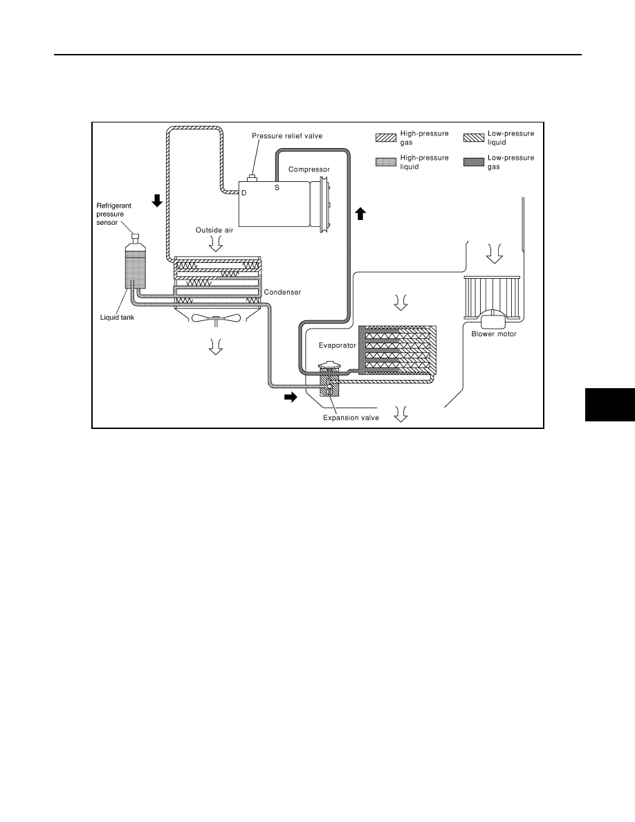
System Diagram
INFOID:0000000005249878
System Description
INFOID:0000000005249879
REFRIGERANT CYCLE
Refrigerant Flow
The refrigerant flows from the compressor, through the condenser with liquid tank, through the evaporator, and
back to the compressor. The refrigerant evaporation in the evaporator is controlled by an externally equalized
expansion valve, located inside the evaporator case.
Freeze Protection
To prevent evaporator from freezing up, the evaporator air temperature is monitored, and the voltage signal to
the unified meter and A/C amp. makes the A/C relay go OFF and stop the compressor.
REFRIGERANT SYSTEM PROTECTION
Refrigerant Pressure Sensor
The refrigerant system is protected against excessively high- or low-pressures by the refrigerant pressure sen-
sor, located on the liquid tank. The refrigerant pressure sensor detects the pressure inside the refrigerant line
and sends the voltage signal to the ECM if the system pressure rises above, or falls below the specifications.
The high-pressure side detected by refrigerant pressure sensor is approximately 3,120 kPa (31.8 kg/cm
2
, 452
psi) or more when the engine speed is 1500 rpm or more. It is approximately 2,740 kPa (27.9 kg/cm
2
, 397 psi)
when the engine speed is less than 1,500 rpm. When it is approximately 120 kPa (1.2 kg/cm
2
, 17 psi) or less,
ECM turns the A/C relay to OFF and stops the compressor.
Pressure Relief Valve
The refrigerant system is also protected by a pressure relief valve, located in the rear head of the compressor.
The release port on the pressure relief valve automatically opens and releases refrigerant into the atmosphere
when the pressure of refrigerant in the system increases to an unusual level [more than 3,628 kPa (37 kg/cm
2
,
526 psi)].
RJIA1552E