Infiniti FX35, FX50 (S51). Manual - part 1096


  Index      Infiniti     Infiniti FX35, FX50 (S51) - service repair manual 2010 year


Search            


Content   ..  1094  1095  1096  1097   ..


Infiniti FX35, FX50 (S51). Manual - part 1096


FRONT COIL SPRING AND SHOCK ABSORBER

FSU-31

< REMOVAL AND INSTALLATION >

[AWD]

C

D

F

G

H

I

J

K

L

M

A

B

FSU

N

O

P

Check the following items, and replace the part if necessary.
• Shock absorber for deformation, cracks or damage.
• Piston rod for damage, uneven wear or distortion.
• Oil leakage.

Shock Absorber Mounting Bracket and Rubber Parts Inspection

Check shock absorber mounting bracket for cracks and rubber parts for wear. Replace it if necessary

Coil Spring

Check coil spring for cracks, wear or damage. Replace it if necessary.

Disposal

INFOID:0000000005246449
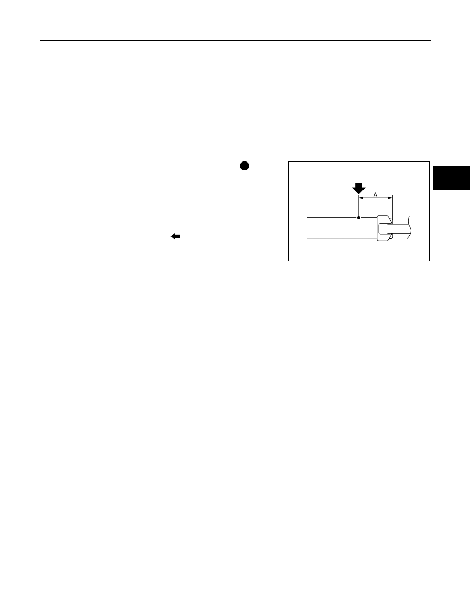
1.

Set shock absorber horizontally with the piston rod fully extended.

2.

Drill 2 – 3 mm (0.08 – 0.12 in) hole at the position (

) from top

as shown in the figure to release gas gradually.

CAUTION:

• Wear eye protection (safety glasses).
• Wear gloves.
• Be careful with metal chips or oil blown out by the com-

pressed gas.

NOTE:
• Drill vertically in this direction (

).

• Directly to the outer tube avoiding brackets.
• The gas is clear, colorless, odorless, and harmless.

3.

Position the drilled hole downward and drain oil by moving the piston rod several times.

CAUTION:

Dispose of drained oil according to the law and local regulations.

A

: 20 – 30 mm (0.79 – 1.18 in)

NNEIA0021ZZ

FSU-32

< REMOVAL AND INSTALLATION >

[AWD]

TRANSVERSE LINK

TRANSVERSE LINK

Exploded View

INFOID:0000000005246450

Removal and Installation

INFOID:0000000005246451

REMOVAL

1.

Remove tires with power tool.

2.

Remove shock absorber. Refer to 

FSU-27, "Exploded View"

.

3.

Temporarily install upper link and steering knuckle. Refer to 

FAX-16, "Exploded View"

.

4.

Remove front cross bar.

5.

Remove transverse link from steering knuckle.

6.

Set suitable jack under transverse link.

7.

Remove transverse link.
NOTE:
If removing transverse link mounting bolt (front side) is difficult, rotating steering wheel and remove steer-
ing outer socket. Refer to 

ST-26, "Exploded View"

.

INSTALLATION

Note the following, and install in the reverse order of removal.
• Never tap on the ball joint cap of the stabilizer connecting rod with a hammer or a similar item when inserting

the stabilizer connecting rod into the transverse link.

• Perform final tightening of bolts and nuts at the front suspension member installation and shock absorber

lower side (rubber bushing), under unladen conditions with tires on level ground.

Inspection

INFOID:0000000005246452

INSPECTION AFTER REMOVAL

Appearance

Check the following items, and replace the part if necessary.
• Transverse link and bushing for deformation, cracks or damage.
• Ball joint boot for cracks or other damage, and also for grease leakage.

Ball Joint Inspection

1.

Stopper arm bushing

2.

Upper link

3.

Front suspension member

4.

Transverse link

5.

Front cross bar

Refer to 

GI-4, "Components"

 for symbols in the figure.

JPEIA0110GB

TRANSVERSE LINK

FSU-33

< REMOVAL AND INSTALLATION >

[AWD]

C

D

F

G

H

I

J

K

L

M

A

B

FSU

N

O

P

Manually move ball stud to confirm it moves smoothly with no binding.

Swing Torque Inspection

NOTE:
Before measurement, move ball stud at least ten times by hand to check for smooth movement.
• Hook a spring balance (A) at cotter pin mounting hole. Confirm

spring balance measurement value is within specifications when
ball stud begins moving.

- If swing torque exceeds standard range, replace transverse link

assembly.

Rotating Torque Inspection

• Attach mounting nut to ball stud. Make sure that rotating torque is

within specifications with a preload gauge (A) [SST: 3127S000 (J-
25765-A)]. 

- If rotating torque exceeds standard range, replace transverse link

assembly.

Axial End Play Inspection

• Move tip of ball stud in axial direction to check for looseness.

- If axial end play exceeds standard range, replace transverse link assembly.

INSPECTION AFTER INSTALLATION

1.

Check shock absorber actuator harness connector for proper connection (with Continuous Damping Con-
trol).

2.

Check wheel sensor harness for proper connection. Refer to 

BRC-131, "FRONT WHEEL SENSOR :

Exploded View"

.

3.

Check wheel alignment. Refer to 

FSU-26, "Inspection"

.

4.

Adjust neutral position of steering angle sensor. Refer to 

BRC-9, "ADJUSTMENT OF STEERING ANGLE

SENSOR NEUTRAL POSITION : Special Repair Requirement"

.

Swing toque

: Refer to 

FSU-39, "Ball Joint"

.

JPEIA0005ZZ

Rotating toque

: Refer to 

FSU-39, "Ball Joint"

.

PDIA1258E

Axial end play

: Refer to 

FSU-39, "Ball Joint"

.

FSU-34

< REMOVAL AND INSTALLATION >

[AWD]

UPPER LINK

UPPER LINK

Exploded View

INFOID:0000000005246453

Removal and Installation

INFOID:0000000005246454

REMOVAL

1.

Remove tires from with power tool.

2.

Remove shock absorber. Refer to 

FSU-27, "Exploded View"

.

3.

Remove upper link and stopper arm bushing.

INSTALLATION

Note the following, and install in the reverse order of removal.
• Perform final tightening of bolts and nuts at the vehicle installation position (rubber bushing), under unladen

conditions with tires on level ground.

Inspection

INFOID:0000000005246455

INSPECTION AFTER REMOVAL

Appearance

Check the following items, and replace the part if necessary.
• Upper link and bushing for deformation, cracks or damage.
• Ball joint boot for cracks or other damage, and also for grease leakage.

Ball Joint Inspection

Manually move ball stud to confirm it moves smoothly with no binding.

Swing Torque Inspection

NOTE:
Before measurement, move ball stud at least ten times by hand to check for smooth movement.

1.

Stopper arm bushing

2.

Upper link

3.

Front suspension member

4.

Transverse link

5.

Front cross bar

Refer to 

GI-4, "Components"

 for symbols in the figure.

JPEIA0110GB


Content   ..  1094  1095  1096  1097   ..