Content .. 1017 1018 1019 1020 ..
Infiniti FX35, FX50 (S51). Manual - part 1019
EXL-72
< DTC/CIRCUIT DIAGNOSIS >
[XENON TYPE]
XENON HEADLAMP
XENON HEADLAMP
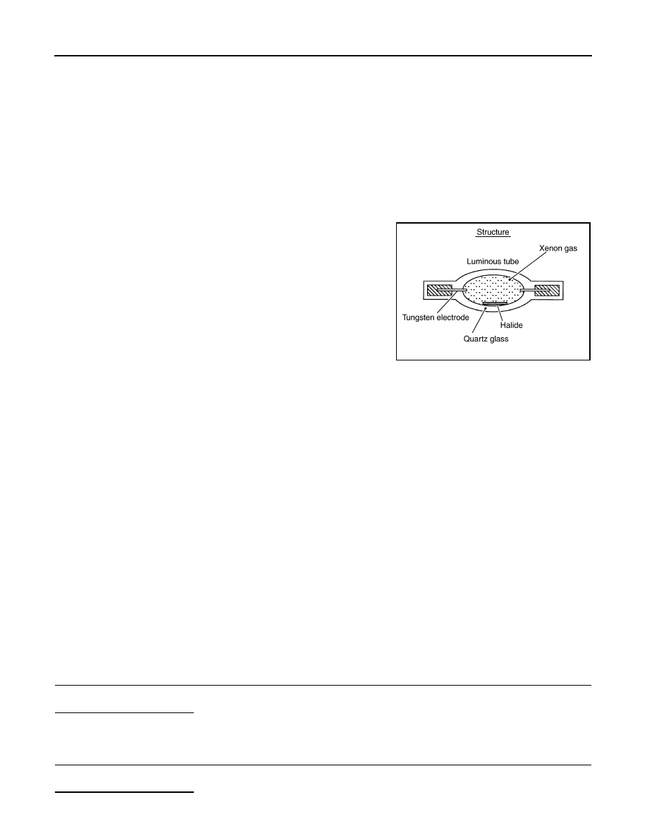
Description
INFOID:0000000005244736
OUTLINE
• The lamp light source is by the arch discharge by applying high voltage into the xenon gas-filled bulb instead
of the halogen bulb filament.
• Sight becomes more natural and brighter because the amount of light are gained adequately and the color of
light is sunshine-like white.
• The xenon bulb drops the amount of light, repeats blinking, and illuminates in red if the bulb reaches the ser-
vice life.
ILLUMINATION PRINCIPLE
1.
Discharging starts in high voltage pulse between bulb elec-
trodes.
2.
Xenon gas is activated by current between electrodes. Pale light
is emitted.
3.
The luminous tube (bulb) temperature elevates. Evaporated
halide is activated by discharge. The color of light changes into
white.
NOTE:
• Brightness and the color of light may change slightly immediately
after the headlamp turned ON until the xenon bulb becomes sta-
ble. This is not malfunction.
• Illumination time lag may occur between right and left. This is not
malfunction.
PRECAUTIONS FOR TROUBLE DIAGNOSIS
Representative malfunction examples are, "Light does not turn ON", "Light blinks", and "Brightness is inade-
quate." The cause often be the xenon bulb. Such malfunctions, however, are occurred occasionally by HID
control unit malfunction or lamp case malfunction. Specify the malfunctioning part with diagnosis procedure.
WARNING:
• Never touch the harness, HID control unit, the inside and metal part of lamp when turning the head-
lamp ON or operating the light switch.
• Never work with wet hands.
CAUTION:
• Never perform HID control unit circuit diagnosis with a circuit tester or an equivalent.
• Temporarily install the headlamp on the vehicle. Connect the battery to the connector (vehicle side)
when checking ON/OFF status.
• Disconnect the battery negative terminal before disconnecting the lamp socket connector or the har-
ness connector.
• Check for fusing of the fusible link(s), open around connector, short, disconnection if the symptom
is caused by electric error.
NOTE:
• Turn the switch OFF once before turning ON, if the ON/OFF is inoperative.
• The xenon bulb drops the amount of light, repeats blinking, and illuminates in red if the bulb reaches the ser-
vice life.
Diagnosis Procedure
INFOID:0000000005244737
1.
CHECK XENON BULB
Install the normal bulb to the applicable headlamp. Check that the xenon bulb is turned ON.
Is the headlamp turned ON?
YES
>> Replace the xenon bulb.
NO
>> GO TO 2.
2.
CHECK HID CONTROL UNIT
Install the normal HID control unit to the applicable headlamp. Check that the lamp is turned ON.
Is the headlamp turned ON?
JPLIA0421GB