Infiniti FX35, FX50 (S51). Manual - part 67
AV
AV CONTROL UNIT
AV-41
< ECU DIAGNOSIS INFORMATION >
[WITHOUT NAVIGATION]
C
D
E
F
G
H
I
J
K
L
M
B
A
O
P
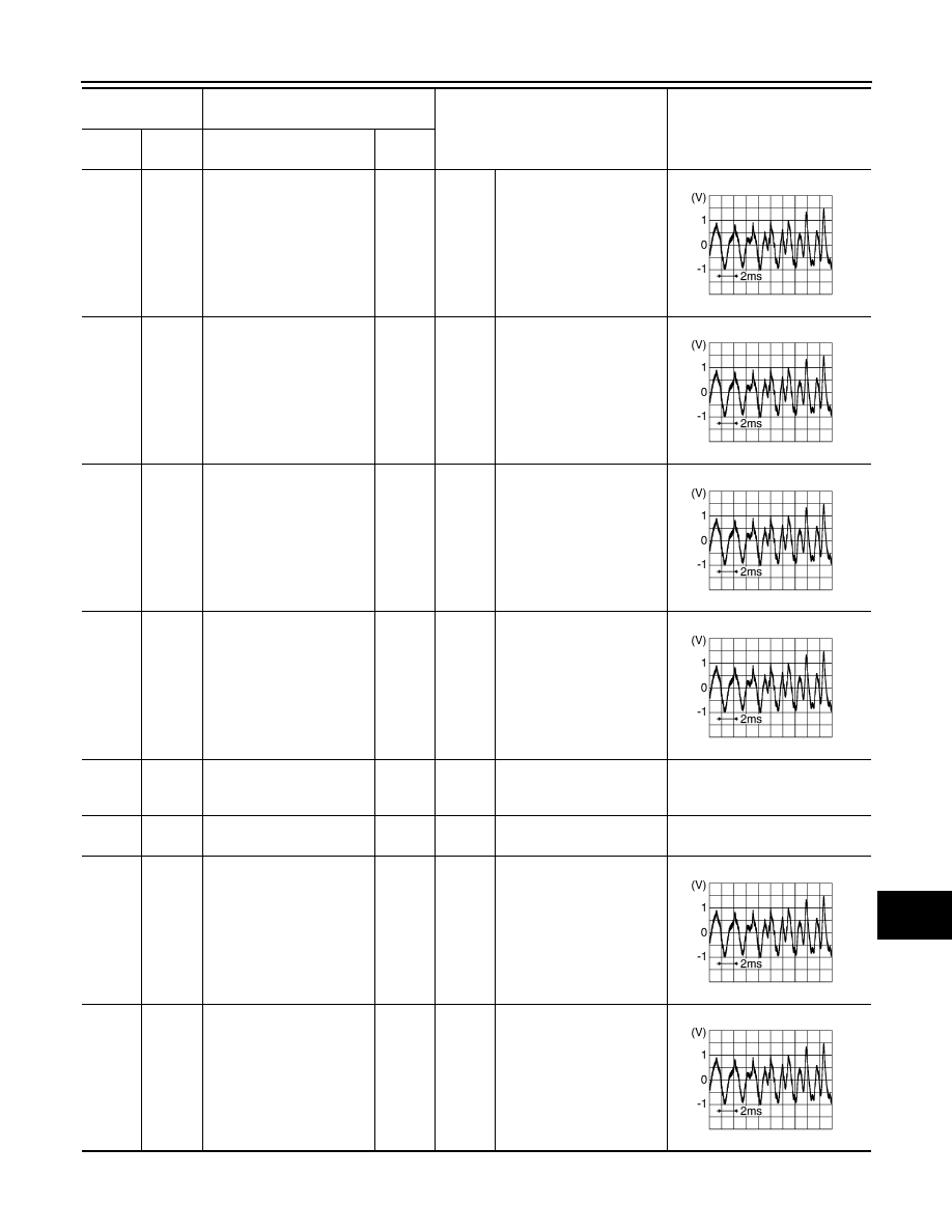
103
(W)
102
(B)
AUX sound signal LH
Input
Ignition
switch
ON
When AUX mode is select-
ed.
104
(R)
102
(B)
AUX sound signal RH
Input
Ignition
switch
ON
When AUX mode is select-
ed.
108
(BR)
114
(Y)
Sound signal rear RH
Output
Ignition
switch
ON
Sound output.
109
(R)
115
(G)
Sound signal front RH
Output
Ignition
switch
ON
Sound output.
110
(V)
Ground
Amp. ON signal
Output
Ignition
switch
ACC
—
12.0 V
111
(B)
—
Shield
—
—
—
—
112
(V)
118
(LG)
Sound signal rear LH
Output
Ignition
switch
ON
Sound output.
113
(P)
119
(L)
Sound signal front LH
Output
Ignition
switch
ON
Sound output.
Terminal
(Wire color)
Description
Condition
Reference value
(Approx.)
+
–
Signal name
Input/
Output
SKIB3609E
SKIB3609E
SKIB3609E
SKIB3609E
SKIB3609E
SKIB3609E