Infiniti FX35, FX50 (S51). Manual - part 66


  Index      Infiniti     Infiniti FX35, FX50 (S51) - service repair manual 2010 year


Search            


Content   ..  64  65  66  67   ..


Infiniti FX35, FX50 (S51). Manual - part 66


AV

AV CONTROL UNIT

AV-37

< ECU DIAGNOSIS INFORMATION >

[WITHOUT NAVIGATION]

C

D

E

F

G

H

I

J

K

L

M

B

A

O

P

7

(V)

Ground

ACC power supply

Input

Ignition 

switch 

ACC

Battery voltage

9

(R)

Ground

Illumination signal

Input

Ignition 

switch 

OFF

Lighting switch is OFF.

0 V

Lighting switch is ON.

12.0 V

16

(L)

15

(B)

Steering switch signal B

Input

Ignition 

switch 

ON

Keep pressing VOL DOWN 
switch.

0 V

Keep pressing VOL UP 
switch.

0.7 V

Keep pressing 

 switch.

1.3 V

Except for above.

3.3 V

19

(Y)

Ground

Battery power supply

Input

Ignition 

switch 

OFF

Battery voltage

20

(B)

Ground

Ground

Ignition 

switch 

ON 

0  V

36

(O)

Ground

Signal VCC

Output

Ignition 

switch 

ACC

8.8 V

37

(LG)

Ground

Signal ground

Ignition 

switch 

OFF

0  V

38

(R)

Ground

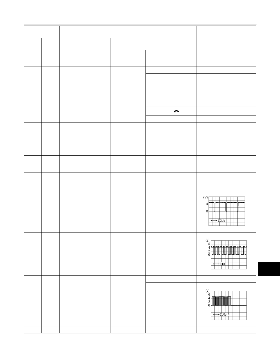
Horizontal synchronizing 
(HP) signal

Input

Ignition 

switch 

ON 

39

(BR)

Ground

Communication signal
(DISP

CONT)

Input

Ignition 

switch 

ON

When adjusting display 
brightness.

40

(B)

Ground

RGB area (YS) signal

Output

Ignition 

switch 

ON 

At RGB image is displayed.

5.0 V

At AUX image is displayed.

41

Shield

Terminal

(Wire color)

Description

Condition

Reference value

(Approx.)

+

Signal name

Input/

Output

SKIB3601E

PKIB5039J

PKIB4948J

AV-38

< ECU DIAGNOSIS INFORMATION >

[WITHOUT NAVIGATION]

AV CONTROL UNIT

42

(G)

Ground

RGB synchronizing signal

Output

Ignition 

switch 

ON 

43

(B)

Ground

RGB signal (R: red)

Output

Ignition 

switch 

ON 

Start Confirmation/Adjust-
ment mode, and then dis-

play color bar by selecting 

“Color Spectrum Bar” on 

Display Diagnosis screen.

44

(W)

Ground

RGB signal (G: green)

Output

Ignition 

switch 

ON 

Start Confirmation/Adjust-
ment mode, and then dis-

play color bar by selecting 

“Color Spectrum Bar” on 

Display Diagnosis screen.

45

(R)

Ground

RGB signal (B: blue)

Output

Ignition 

switch 

ON 

Start Confirmation/Adjust-
ment mode, and then dis-

play color bar by selecting 

“Color Spectrum Bar” on 

Display Diagnosis screen.

46

(V)

Ground

Composite image signal 
ground

Ignition 

switch 

ON

0  V

47

(SB)

Ground

Composite image signal

Output

Ignition 

switch 

ON

At camera image is dis-
played.

48

(Y)

Ground

Inverter VCC

Output

Ignition 

switch 

ACC

8.8  V

49

(BR)

Ground

Inverter ground

Ignition 

switch 

OFF

0  V

Terminal

(Wire color)

Description

Condition

Reference value

(Approx.)

+

Signal name

Input/

Output

SKIB3603E

JSNIA1029ZZ

JSNIA1030ZZ

JSNIA1031ZZ

SKIB2251J

AV

AV CONTROL UNIT

AV-39

< ECU DIAGNOSIS INFORMATION >

[WITHOUT NAVIGATION]

C

D

E

F

G

H

I

J

K

L

M

B

A

O

P

50

(W)

Ground

Vertical synchronizing (VP) 
signal

Input

Ignition 

switch 

ON 

51

(Y)

Ground

Communication signal
(CONT

DISP)

Output

Ignition 

switch 

ON

When adjusting display 
brightness.

52

Shield

57

Shield

58

Shield

61

(Y)

Ground

AUX image signal

Input

Ignition 

switch 

ON 

At AUX image is displayed.

62

(W)

Ground

Camera image signal

Input

Ignition 

switch 

ON

At camera image is dis-
played.

63

Shield

69

(BR)

Ground

AUX image signal ground

Ignition 

switch 

ON 

0  V

70

Shield

72

(B)

Camera ground

Ignition 

switch 

ON

0  V

73

(R)

Ground

Camera power supply

Output

Ignition 

switch 

ON

At camera image is dis-
played.

76

(LG)

AV communication signal 
(L)

Input/

Output

Terminal

(Wire color)

Description

Condition

Reference value

(Approx.)

+

Signal name

Input/

Output

SKIB3598E

PKIB5039J

SKIB2251J

SKIB2251J

SKIB2251J

AV-40

< ECU DIAGNOSIS INFORMATION >

[WITHOUT NAVIGATION]

AV CONTROL UNIT

77

(SB)

AV communication signal 
(H)

Input/

Output

78

(LG)

AV communication signal 
(L)

Input/

Output

79

(SB)

AV communication signal 
(H)

Input/

Output

80

(P)

CAN–L

Input/

Output

81

(L)

CAN–H

Input/

Output

82

(BR)

Ground

Switch ground

Ignition 

switch 

ON

0  V

86

Shield

87

(L)

88

(P)

TEL voice signal

Input

Ignition 

switch 

ON

During voice guide output 

with the 


 switch 

pressed.

92

(R)

Ground

Vehicle speed signal (8-
pulse) 

Input

Ignition 

switch 

ON

When vehicle speed is ap-
prox. 40 km/h (25 MPH)

NOTE:
Maximum voltage may be 12.0 V 
due to specifications (connected 
units).

93

(V)

Ground

Parking brake signal

Input

Ignition 

switch 

ON

Parking brake is ON.

4.5 V

Parking brake is OFF.

0 V

94

(O)

Ground

Reverse signal

Input

Ignition 

switch 

ON

Shift the selector lever to R 
position.

12.0 V

Shift the selector lever oth-
er than R position.

0 V

95

(G)

Ground

Ignition signal

Input

Ignition 

switch 

ON

Battery voltage

96

(SB)

Ground

Disk eject signal

Input

Ignition 

switch 

ON

Pressing the eject switch.

0 V

Except for above.

5.0 V

Terminal

(Wire color)

Description

Condition

Reference value

(Approx.)

+

Signal name

Input/

Output

SKIB3609E

SKIA6649J


Content   ..  64  65  66  67   ..